Chapter 9. Microcontroller Hardware and Software
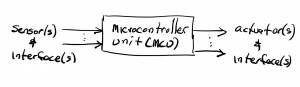
We now introduce the topic of embedded microcontrollers which are small, low-power computers on a single integrated chip (IC). Microcontroller units (MCUs) are found today in many different products ranging from robots to automobile electronics to electric toothbrushes to programmable coffee pots. One estimate suggests that a typical automobile, and a typical home in a developed country each have more than 30 MCUs in use. We will discuss how to use software scripts (or firmware) uploaded to MCUs to create flexible and reconfigurable systems for sensing variables and controlling objects. Just a few examples of variables we might want to sense and the corresponding sensors we might use include: temperature, via a thermistor); light intensity, via CDS cell, photodiode, or phototransistor); and object distance via a sonar. MCU software processes the information collected by these sensors on MCU data input lines and instructs the MCU to control objects in response via MCU data output lines. Some examples of objects we might want to control include motors, fans, LEDs and lights, door locks, engine ignitions, alarms, various displays, etc…
Earlier in this text, we implemented a hard-wired sensing/actuating circuit using a light sensor and a variable-speed motor.
That circuit used a CDS cells as a light sensor and a small DC motor as an actuator. An op amp circuit was used to process the sensor signal and generate a control voltage for the motor. The CDS cell was arranged in a voltage divider circuit soas to convert the light intensity into a voltage for the op amp input. The op amp output voltage was connected to a transistor driver circuit that converted the op amp output signal into a voltage and current signal suitable to power the motor. The two different wiring configurations shown below resulted in circuits that would either turn the motor and off when light on the CDS cell exceeded a threshold level (upper figure) or adjust the motor speed in proportion to the intensity of the light shining on the CDS sensor (lower figure).
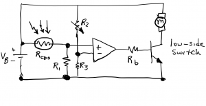
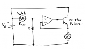
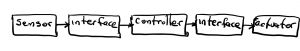
Note that the sensor, op amp, and actuator are common to both circuits, however the functionality and the specifics of the wiring of the two circuits were different: one circuit functioned, and was wired, to turn a motor on and off based on a threshold light level whereas the other circuit functioned, and was wired, to convert light intensity to motor speed. A more abstract, or higher-level, way to visualize these two circuits without the wiring details is via a functional block diagram connecting the sensor, controller, and actuator through interfaces as shown below. In this diagram, the sensor block represents the CDS cell, the controller block represents the op amp, and the actuator block represents the motor. The first interface represents the voltage divider circuit that enables the CDS cell to connect to the op amp. The second interface block represents the transistor driver circuit that connects the motor to the op amp output. This is a generic diagram that can be used to represent a variety of sense/response control systems. The light sensor circuit we have described relies on a hard-wired analog control circuit for its operation. The “hard wiring” represents the physical wires connecting sensor+interface and interface+actuator subsystems to the controller. The two different implementations described above have different wiring configurations, and changing the circuit from one to the other or requires changing the circuit wiring. Changing the sensitivity of the on/off circuit also requires a hardware change in the form of a change in a resistor value or an adjustment to a potentiometer to change the reference voltage into the – terminal of the op amp. For a simple circuit such as this motor controller, the wiring changes are modest; for more complicated circuits, the changes can necessitate a complete redesign and re-build of the circuit.
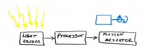
Rather than building sense/actuator control circuits from a collection of hard-wired components, the same functionality can often be achieved by using a microcontroller capable of taking input from one or more sensors, through appropriate interfaces, and generating one or more output control signals. These output signals, through appropriate interfaces, control one or more actuators. The control functionality is based on software uploaded to the MCU. The following system, implemented using an Arduino Uno MCU development board, can implement the same functionality as the previous two motor control circuits without requiring any changes in wiring. Different software scripts can be uploaded to the ATmega328P MCU on the Arduino Uno board to achieve different functionality using a common wiring configuration.
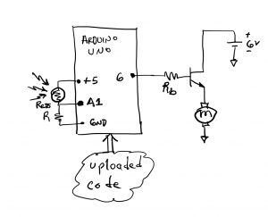
The MCU on the Arduino Uno implements a set of software instructions that specify how the input signals are to be processed and how the output signals are to behave. In this specific example, the Arduino Uno takes the voltage between RCDS and R as an analog input on pin A1, processes this value, and then generates a control voltage as a digital signal on output pin #6, and this output drives the motor through the low-side NPN transistor switch. A key difference between this implementation and the hard-wired circuits shown above is that the specific functionality of the MCU-based system can be changed with software rather than requiring hardware changes.