2.4 Current and Voltage Sources
Current Sources. An independent current source is an idealized source of current that maintains a specified current through its terminals independent of the voltage across its terminals and independent of any other circuit elements connected to it. The schematic symbol for a current source is a circle with an arrow depicting the current reference direction, as shown. Direct current, or DC, current sources are constant, non-time varying currents that are typically denoted using capitalized variables, such as  or with a subscript such as
  , whereas alternating current, or AC current sources are time-varying currents, denoted using lower-case variables, such as
  or
or  . DC and AC currents are described below.

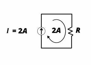
Direct current. The following circuit shows a current source  which causes a current of
  to flow clockwise in the circuit loop in fig. 2.30.
A plot of this current as a function of time is shown below between  and
and  . Clearly,
  represents a non time-varying waveform.
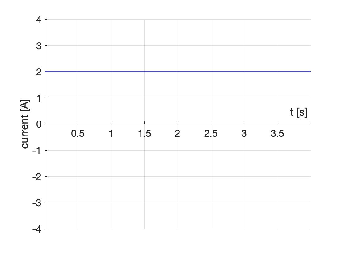
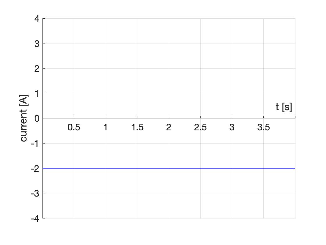
Figure 2.32 shows the same circuit with a  current source instead of the
  current source. In this circuit, flows clockwise in the circuit loop. This is electrically equivalent to flowing counter-clockwise in the loop.
 , or , to flow counter-clockwise in the circuit loop
A plot of this current waveform versus time is shown below.
Figures 2.31 and 2.33 are both examples of direct current or DC waveforms. (Sometimes we say “DC current”, which, though redundant, is common usage.) Direct currents do not vary with time, and they always flow in one direction in a circuit loop.
Alternating Current. Some current sources, such as the current associated with an electric wall outlet driving a household appliance, alternate between positive and negative values with time. Consider the circuit of fig. 2.34 which is driven by a current source having a sinusoidal waveform 

A plot of versus time reveals that this current waveform alternates between positive and negative values as time increases. When  or any integer, the argument of the cosine function is an integer multiple of
  and achieves its maximum value of 2 amperes. This waveform thus repeats every second, and it has a frequency of one cycle per second or 1 Hz.
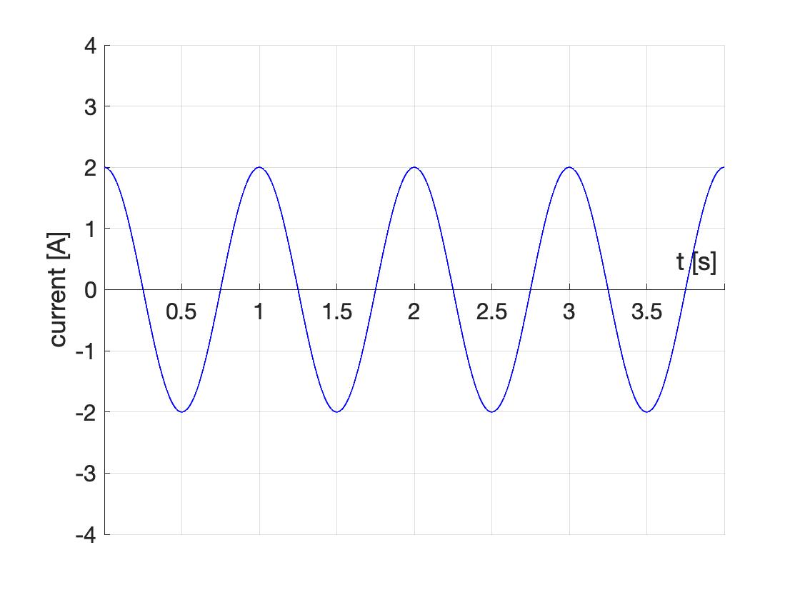
During the times when the current is positive, charges flow clockwise in the circuit loop; conversely, charges flow counterclockwise during the times when the current is negative. Since the direction of current flow alternates direction between the positive and negative excursions of the sinusoid, this current waveform is referred to as an alternating current or AC waveform.
Voltage sources. An independent voltage source is an idealized model of a voltage source that maintains a fixed electric potential difference (a fixed voltage) between its terminals, independent of the current through the terminals and independent of anything else connected to it. A 1.5V AA battery is often modeled as such an ideal voltage source, meaning that it could, theoretically, provide infinite current, for all time. In practice, batteries are limited in the amount of current they can actually provide and of course they are limited in the amount of energy they can provide before they are either discarded (primary batteries) or “recharged” (secondary batteries). However the independent voltage source model can often be used to model the behavior of a real battery for circuit analysis purposes. The schematic symbols for independent voltage sources are shown below for a battery (right) and a more general voltage source that might vary as a function of time (left). We refer to a constant, non time-varying voltage source as a “DC voltage” and a time varying voltage source as an “AC voltage”. “DC voltage” and “AC voltage” literally mean “direct current voltage” and “alternating current voltage” which are both grammatically meaningless; the terms are used owing to the fact that constant voltages produce DC currents while voltages that alternate between positive and negative values produce AC currents. DC voltages are typically described using capital letters, such as  or
or  , whereas AC voltages are typically described with lower-case variables, such as
  . The subscripts
  and
and  in these examples can be helpful to avoid confusing a voltage variable from the voltage unit symbol , for volts. Often, the time dependence of is omitted in equations, and
  is written instead; whenever a lower-case variable is used, it is understood to be an AC waveform, and such waveforms inherently vary with time. Examples of DC and AC voltage waveforms are given below.

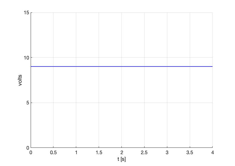
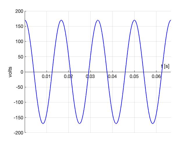
DC and AC voltages. The DC voltage for a 9V battery, is plotted in fig. 2.37 as a function of time. The AC voltage waveform for an electrical wall outlet is shown on fig. 2.38. This particular waveform will be discussed in greater detail in the next chapter.
Dependent voltage and current sources are ideal sources having values dependent on some other quantity in a circuit. The schematic symbol for dependent sources is a diamond, as shown. These symbols are used in schematics for both AC and DC dependent sources.

As an example of a dependent voltage source, the circuit model for an operational amplifier (discussed later in this text) is shown below. In this model, the voltage depends on the difference in voltage at the nodes labeled  and
and  , elsewhere in the circuit.

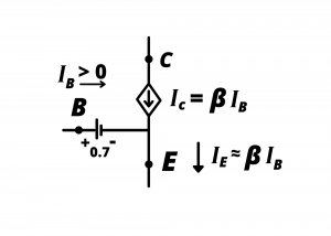
An example of a dependent current source is a bipolar junction transistor operated in the active region (discussed later in this text). The current is dependent on the current elsewhere in the circuit and therefore the diamond symbol is used.