
4.4 Rectifier diode
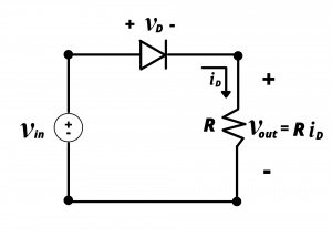
Rectifier diode. Diodes are often used as rectifiers in power supply circuits to convert an AC voltage to a voltage containing an AC and a DC component. A low-pass filter then removes the AC component, resulting in a DC output voltage. Consider the following circuit with AC input voltage  . Assume that the diode has a turn-on voltage
  , which is typical for rectifier diodes. The input waveform oscillates between peak values of
  and
and  . During positive voltage excursions of the sine wave, the diode will be forward biased as long as
  , and during negative excursions of the sine wave, the diode will be reverse biased. Because the turn on voltage is small compared to the peak value of
  , we can ignore it with relatively little error, and model the diode using the ideal diode model.
 has a DC value of zero. The output waveform
  has a non-zero DC value as a result of the diode.
According to the ideal diode model, during positive voltage excursions of the input sinusoid, the diode behaves like a short circuit, and input voltage is therefore applied directly across the load resistor, so that  whenever
  . Conversely, during negative excursions of the input sinusoid, the diode behaves like an open circuit; in this case, the input voltage is dropped across the diode. Since the input voltage is dropped across the diode, the voltage drop across the resistor is 0, and
  whenever
  . Plots of the input and output waveforms are shown in figure 4.29. Note that the input waveform has an average value of zero, hence it has no DC component. The output waveform is always positive, so it must have a non-zero average value, hence it has a non-zero DC component. If the output waveform were filtered, the time-varying component could be eliminated leaving just the DC component. This circuit, which creates a non-zero DC component in the output waveform by removing the negative half of the input sinusoid, is called a “half-wave rectifier” circuit.

