2.6 Circuit Laws: KCL and KVL
We now introduce two laws for analyzing circuits that we will be using for the duration of this text.
Kirchoff’s Current Law. We previously defined a node in a circuit as a point where two or more circuit elements are connected together. Kirchoff’s current law (typically written “KCL”) specifies that the the sum of all currents entering a node must equal the sum of all currents exiting a node.
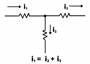
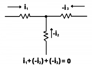
Put another way, the net current entering (or exiting) any circuit node must equal zero. This law amounts to a statement of conservation of charge: if the net current entering any node were non-zero, there would be a net buildup of charge at a point in a circuit over time. The analogy with a hydraulic piping system is helpful: if a series of pipes come together at a junction, the total fluid flow, in gallons per minute or cubic meters per second, entering the junction must equal the total fluid flow exiting the junction, otherwise there would be a buildup of fluid over time. Figure 2.47 is redrawn below to show all currents entering the circuit node with no currents exiting the node. KCL then specifies that the total current entering the node is  . Note that negative signs are used for
  and
and  to represent the currents of Figure 2.47 as entering the node when we draw Figure 2.48.
Implication for circuit elements connected in series. We previously defined series circuit elements as elements connected end-to-end, with no additional path for current to flow. Implicit in this definition is that the currents in series-connected elements are identical.
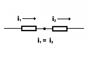
This can be shown via straightforward application of Kirchoff’s Current Law, where, for the single node in Figure 2.49,  by KCL. This can be readily extended to more than two circuit elements combined in series, allowing us to state: all circuit elements connected in series have the same value of current.
Examples
Determine the value of current  in the circuit shown:
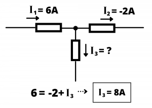
Solution: letting the sum of currents entering the node equal the sum of currents exiting the node, we have:  or
or  A.
A.
Determine the value of the current in the circuit shown:
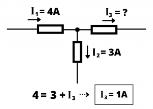
Solution: proceeding as in the previous example:  or
or  A.
A.
Note that in these two examples and in Figures 2.50 and 2.51, we use the variables  ,
,  and whereas we used variables
  , , and in figures 2.47 and 2.48. This is keeping with our convention of using upper case variables to represent DC values, as in these two examples, while using lower case variables to represent the more general case of AC and mixed AC+DC values.
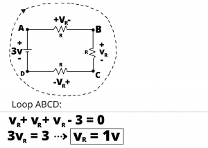
Kirchoff’s Voltage Law. We previously defined a loop in a circuit as a closed path starting at a node, proceeding through circuit elements, ultimately returning to the starting node. Kirchoff’s voltage law (KVL) stipulates that the sum of voltages encountered traversing any closed circuit loop must equal zero. This law amounts to a statement of conservation of energy. The circuit shown in figure 2.52 has four series-connected elements and four nodes, which we label  .
.
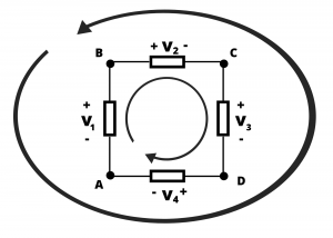
Two loops are shown: a clockwise inner-loop and a counter-clockwise outer loop. Applying KVL clockwise around the inner-loop, starting at node A and proceeding through nodes B, C, and D, and back to A (we write this as  ), we have:
(1) 
Note that we use the first voltage polarity encountered to determine whether to add or subtract the voltage of an element between nodes, thus, between A and B, we have  , while between B and C we have
  , since we first encounter the
  terminal of
  and the
  terminal of
  when proceeding clockwise around loop . Similarly, we could apply KVL counterclockwise around the outer-loop
  , with the result
(2) 
Inspection of equations (1) and (2) reveals that they are equivalent. It does not matter where in a closed loop one starts summing a KVL equation or in which direction (clockwise or counter-clockwise) one proceeds. KVL sums around  ,
,  ,
,  ,
,  , etc… all result in the same KVL equation.
Examples
Example: Write the KVL equation around the loop ABCD in the circuit shown.
Example: Use KVL to solve for the voltage  in the circuit shown, where is the voltage drop across the three resistors,
  .
.
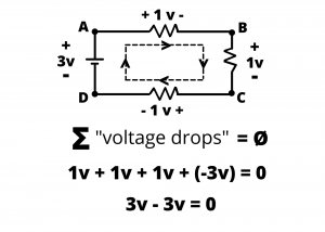
Implication for circuit elements connected in parallel: We previously defined parallel circuit elements as elements having their two ends connected to each other as shown, for example, in figure 2.55. Implicit in this definition is that the voltages across parallel-connected elements are identical. This can be shown via straightforward application of Kirchoff’s Voltage Law, where, for the single loop circuit shown, KVL around loop ABA gives us  which results in
  .
.
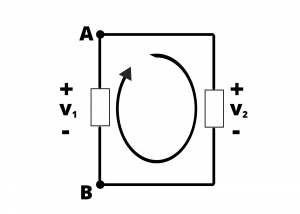
This can be readily extended to more than two circuit elements combined in parallel, allowing us to state: all circuit elements connected in parallel have the same voltage across their terminals.
Examples
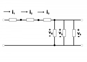
Example: In the circuit shown in Figure 2.56, which elements are connected in series and which are in parallel? What are the implications for the voltages and currents in the circuit?
Solution: Elements 1, 2, and 3 are connected in series, therefore,  . Elements 4, 5, and 6 are connected in parallel, therefore
  .
.