
4.3 Diode Circuit Models
Diodes present a circuit analysis challenge compared to linear devices (such as resistors) owing to the complex shape of the diode  curve. Unlike a resistor, there isn’t an exact analytical expression relating voltage and current in a diode that can be written down and used in KVL and KCL and node voltage analyses described in chapter 3. Graphical techniques, such as the load line analysis presented in the previous section, can provide useful approximate results, but it can be cumbersome to rely on graphs and line plotting. In this section, we develop a set of simplifying models of diode behavior that can be used to support circuit analysis.
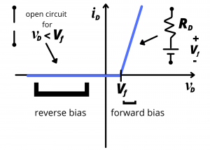
Piecewise linear model. If you haven’t seen the video from the previous section titled “redLEDIVburntest” go back and view that now, as it will help you to understand this section. Figure 4.21 shows a piecewise linear approximation for our red LED curve. For diode voltages less than the “turn on” or “forward” voltage,  , the diode is reverse biased; no light is emitted and no current flows. In this case, the diode behaves like an open circuit. A typical value of for a light-emitting diode is 1.7V. For diode voltages greater than , the diode is forward biased; light is emitted, current flows through the device. The piecewise linear diode model predicts a linear increase in diode current as
  increases beyond . The slope of the linear increase has units of
  or
or  and this represents the reciprocal of the internal resistance of the diode. We previously found that our red LED has a slope of
  , indicating an internal resistance of
  .
.
Equivalent circuit. Recall from the “redLEDIVburntest” video that LED didn’t begin to turn on until was ~. The LED behavior for applied voltage  can be characterized by treating the forward biased diode as a voltage drop, , in series with a resistor,
  . is referred to as the forward voltage of the diode while is called the diode resistance.
To see why a voltage drop series with a resistor models the behavior of a forward biased diode, we consider the characteristic for a circuit comprised of a 1.7 V battery in series with an 8Ω resistor as shown in figure 4.22. Note that the current flows from the + terminal to the – terminal of the 1.7V battery; the battery thus represents a voltage drop.
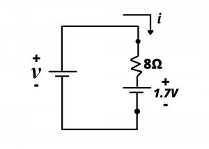
Here, we treat the series combination of the resistor and the  battery as a single, combined circuit element. The characteristic for this circuit element is obtained by analyzing KVL around the loop:
(1) 
and the current is then
(2) 
A Matlab plot of  , in mA, versus
  , in volts, is shown in Figure 4.23 Positive values of , between 0 and 100 mA correspond to
  and are seen to predict the linearly-increasing, forward biased part of the curve shown in figure 4.21. Note, however, that the model of figure 4.22 does not correctly characterize the reverse bias diode behavior, since the model predicts negative values of current for
  . For this region, the diode is modeled, instead, as an open circuit. We thus see that the series combination of a volt battery and a resistance models the forward bias region of the diode, for which >, while an open circuit models the reverse biased region of the diode for which
  , and
, and  .
.

Simple piecewise linear model. A simpler model, shown in Figure 4.24, ignores the forward resistance of the diode and treats the forward biased diode as a voltage source and the negative biased diode as an open circuit. This model neglects the linear increase in current with increasing diode voltage; circuit analysis using this model can over-estimate the actual diode current unless there is resistance in the external circuit biasing the diode, as we discuss in the example circuits below.
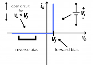
Ideal diode model. An even simpler model treats the diode like a one-way valve as shown in Figure 4.25. In this model, both and are ignored and the diode is treated as an open circuit when  and as a short circuit when
  . This model is most appropriate when the external voltage applied to the diode is large compared to .

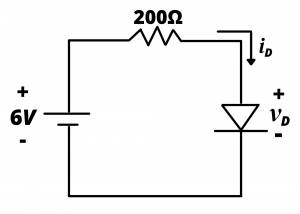
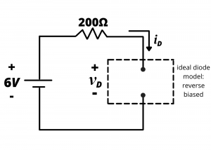
Example: Determine the current in the circuit shown if the diode has a turn-on voltage  . Consider three modeling cases: (a) the ideal diode model; (b) the simple piecewise linear diode model; (b) the piecewise linear model with

Solution:
For part (a) we will use the ideal diode model, in which the diode is modeled as a short circuit under forward bias ( ) and as an open circuit under reverse bias (
 ). It should be clear by this point that the diode is forward biased in this circuit because of the 6V battery. But if we did not know this, we might make an initial guess that the diode is reverse biased. This would result in the circuit of figure 4.26b with an open circuit in place of the diode.
Analysis of figure 4.26b gives:
(3) 
which gives us  when we let in equation (3). This finding is inconsistent with the ideal diode model, which specifies
  . Therefore, we can conclude that our initial guess of a reverse biased diode was incorrect, and the diode must be forward biased as shown in figure 4.26c.

In this case, with , and KVL gives:
(4) 
When we let in equation (4) have obtain the result 
(b) The simple piecewise linear model under the assumption of forward bias is shown in figure 4.26d.
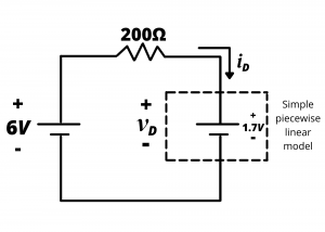
In this case, the forward diode current is  . We first note that this result with
  is consistent with behavior of the simple piecewise linear model under forward bias. Next, we note that this current is significantly less than that the 30mA predicted using the ideal diode model. The ideal diode model is over-predicting the diode current because it neglects the voltage drop across the diode, and this voltage drop is a sizable fraction of the
  voltage supply in this circuit. In a subsequent example, we will look at a case where the supply voltage is substantially higher, and the effect of the forward voltage drop is negligible.
(c) The piecewise linear diode model, with and  , is shown in figure 4.26e.
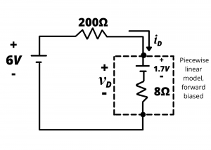
KVL gives
(5) 
This results in  . This result is within
  of the result predicted by the simple piecewise linear model. The reason is that is relatively small compared to the
  current limiting resistor in the circuit.
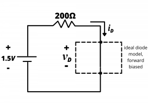
Example: Determine the current through the diode shown in .
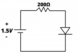
Solution: Since the turn-on voltage of the diode is , and the battery voltage is only  , the diode will be reverse biased. It will therefore behave like an open circuit and the current will be zero. Suppose we had started this solution with the assumption that the diode is forward biased, and we used the simple piecewise linear diode model for analysis. The equivalent circuit is shown in figure 4.27b.

KVL gives
(6) 
which results in a current  . This result is inconsistent with the piecewise linear diode model, which requires when the diode is forward biased. From this analysis, we know that the diode is reverse biased.
Let us now solve this problem using the ideal diode model, assuming forward bias. The circuit shown in Figure 4.27c gives a diode current  . This result, with is consistent with the ideal diode model, however it incorrectly corrects the diode bias state and the resulting current.
The ideal diode model ignores the built-in turn-on voltage of the diode, and that voltage is similar in size to the battery voltage in this problem. Clearly, the model that neglects this voltage will give erroneous results.
