6.3 Open Loop Voltage Comparator
A very common application of an op amp that makes deliberate use of saturation is the voltage comparator. This circuit compares two input voltages and produces a binary output voltage (that is, a voltage that can have only one of two possible values) to indicate which voltage is higher. Consider the circuit shown, with unipolar supply voltage VCC. Assume the op amp is ideal, with infinite open-loop gain, A. The output voltage hits the positive voltage supply rail, VCC volts, whenever the differential input voltage is positive, i.e., when V+>V– . Likewise, the output voltage sits at the ground rail, 0 volts, whenever the differential input voltage is negative, i.e., when V+<V– . If we consider a real op amp, with finite open loop gain, such as A=106, then the output would sit at the positive supply rail whenever V+ exceeds V- by 1 μV, a very small value.

Examples
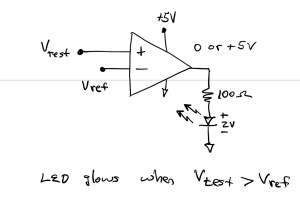
Example: Design an op amp comparator circuit that determines whether a test voltage, Vtest, exceeds a reference voltage, Vref. The circuit should cause an LED to glow whenever Vtest>Vref.
Solution: The op amp is set up as a voltage comparator with inputs Vtest and Vref. (We are not concerned with where these voltages come from in this circuit; in the next chapter, we will examine this using a more detailed circuit.) When powered with a unipolar supply voltage of +5V, the op amp output will be high (+5V) when Vtest>Vref and low (0V or gnd potential) otherwise. An LED at the output of the op amp serves as an indicator, glowing when Vtest>Vref. The 100Ω resistor between the LED anode and the op amp output was chosen to provide a current of ~ 30 mA in the LED circuit, which would result in a bright LED.
Question: in the example just discussed, what value resistor should be used in the output circuit, in place of the 100Ω resistor, if the voltage supply rail of 12 V is used instead of 5V? Assume, for this case, that the LED drops 2 V and should be operated at a current of 10 mA.
Answer: The high-level output from the op amp would be 12V. The resistor would drop 10 V, and the appropriate resistance would be R=V/I=10/.01 = 1000Ω=1kΩ.
Note that the output voltage was assumed to saturate at the voltage supply rail, 5 and 12 volts, in these two examples. We are ignoring the ~ 1 V voltage drop between the supply rail and the saturated output in these examples.
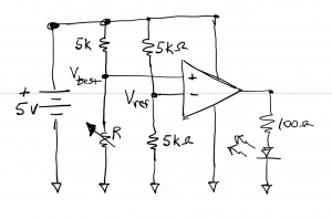
The figure below shows how the previous circuit might be developed using a pair of voltage dividers at the op amp inputs. Op amp voltage rails VCC and ground are connected to the + and – terminals of a 5 volt battery, respectively. Two voltage dividers, each comprised of a pair of resistors in series, are connected in parallel with the battery. In this circuit, Vref=2.5 V and Vtest is determined by the setting of variable resistor R. When R>5kΩ, Vtest>Vref and the output LED will glow.

Below we have another view of the same circuit with the ground symbol used in place of the lower node.
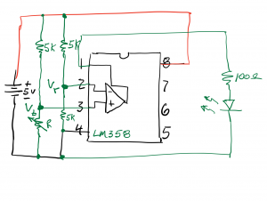
Next, we show a wiring drawing of the circuit using an LM358 Dual Op Amp IC. Only one of the two op amps on this IC is used in the circuit.