
6.2 Op Amp Input-Output Characteristic
Consider the op amp circuit involving an ideal op amp( ) having open loop gain
  with unipolar
  volt power supply as shown:

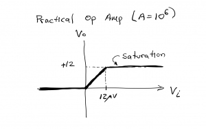
The relationship between the differential input voltage Vi = V+-V– and the output voltage Vo is characterized by the expression  during linear operation, ie, when the op amp is not saturated, which requires Vi< 12 microvolts (12 μV) and V0<12 V for this circuit. The output voltage of this circuit will not exceed the 12 V battery rail voltage; therefore, for differential input values Vi greater than 12 μV, the output voltage remains pinned, or saturated, at 12 V, as shown in the input vs. output plot shown:
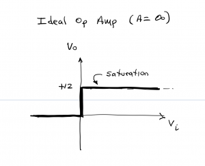
Note that the slope of the Vi vs Vo curve is  for the linear operating region (that is, inputs between 0 and < 12 uV), while the slope is 0 in the saturated regions (input voltage <0 or > 12 uV). An op amp having a larger open loop gain would have a steeper slope in the linear region and achieve saturation for smaller input voltages. If we consider an ideal op amp having gain A=∞, the linear slope would be ∞, meaning that output voltage would saturate at the voltage rail whenever the input voltage Vi is positive, whereas the output would be zero whenever Vi≤0. The input-output relationship for this case is shown below.
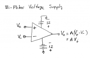
We now consider the case of an op amp having open loop gain A=106 and bipolar power supply voltages of ±12 volts as shown,
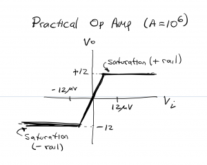
The input-output relationship is characterized by a linear voltage swing between – 12 V and + 12 V, corresponding to input voltages -12 μV to + 12 μV. The op amp saturates at – 12 V for Vi< -12 μV and + 12 V for Vi>12 μV as shown input-output relationship below.
Finally, we consider the bi-polar op amp circuit having infinite open loop gain, A=∞, with the input-output relationship given below.

As a practical matter, the output voltage of an op amp will typically be 1-2 volts lower than the voltage supply rail due to voltage drop across components within the op amp device. (This is analogous to the voltage drop inside a battery resulting from the battery’s internal resistance.) An op amp having unipolar 6 V supply might produce an output voltage ranging from 1 V(low) to 5 V (high). As we shall see in the next section, the op amp comparator with high vs low output (digital output) is an important op amp application in which the precise value of the output voltage is not important. On the other hand, there are many applications where the precise value of the output voltage is important. A bipolar circuit with ± 12V rails would therefore achieve maximum output voltage swings of ±10 or ±11 volts. If the circuit application required output voltage swings as high as ±12V, then a ±15V power supply could be used.
Another important practical topic for op amps is output current. Op amps are not designed to produce a significant amount of output current. The devices we will be workin with are capable of sourcing only a few 10’s of mA. There will be many applications where substantially more current is needed; consider the small DC motor in the ECE361 kit, for example. This motor draws ~ 100-300 mA when unloaded mechanically, and the current draw increases to over 1A when the motor is mechanically loaded down. Driving a motor with a circuit that involves an op amp requires an additional device – a current amplifier of some sort – between the op amp output and the motor power supply terminals. We will examine how transistors serve this role in avsubsequent chapter.
