
3.8 Lab Experiments
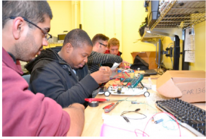
Lab1. The purpose of this set of laboratory experiments is to familiarize students with the components, measurement tools, and wiring techniques used throughout this course. Experiments are conducted using batteries, conducting wire, resistors, your car chassis & motors, and your Arduino Uno, and LED’s all assembled onto a solderless breadboard. You will be using the digital multimeter (DMM) from your kit to measure DC voltages and DC currents in these experiments. Be careful how you hook up the meter, especially when measuring current since it is easy to blow a fuse in the meter by exceeding the current limit.
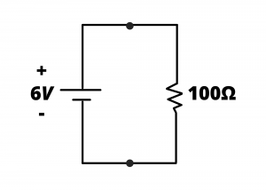
1.1 Build the circuit shown in figure L3.2 on a breadboard using a 6V battery and 100Ω resistor. Measure the voltage across the resistor and the current in the loop. How do these measurements compare with the values you would expect based on theory (ie, Ohm’s law, KCL, and KVL)?
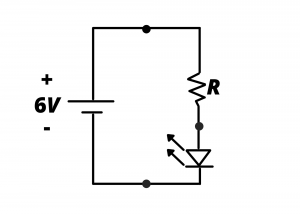
1.2 Build the circuit shown in figure L3.3 comprised of a 6V battery, resistor and a red LED. Measure the voltage across the LED and the current in the loop for  and
and  . The LED should have a voltage drop of ~ 2 V. If you left this circuit running, after how many hours would you expect the LED to stop glowing, given the two values of
  ? Two different approaches to determining this circuit lifetime: one is to assume each battery has ~10kJ of energy, and the other approach is to look up the data sheet for the AA batteries and determine the battery capacity in mAh.
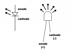
be sure to connect the anode and cathode of the LED correctly. Figure L3.4 should help:
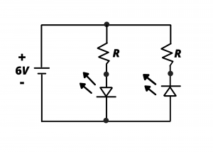
1.3 Build the circuit shown in figure L3.5 by adding an additional resistor and LED to the previous circuit. (Use a resistor value of your choice.) Measure the voltage across and the current through each LED. Measure the current drawn from the battery. How long would the battery last if this circuit were kept running?
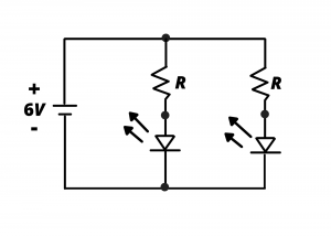
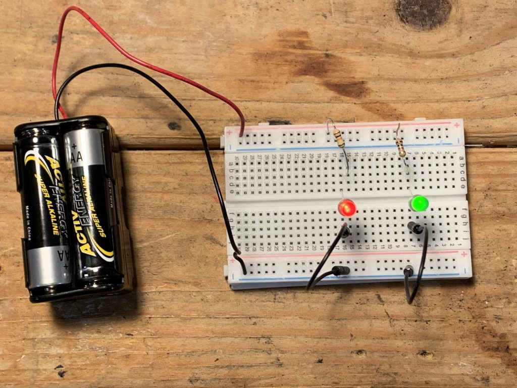
A photo illustrating this circuit assembled onto a breadboard was shown earlier in this chapter. It is also shown in figure L3.6, below.
1.4 Build the circuit of figure L3.5 by reversing the orientation of one of the LED’s. Repeat the voltage and current measurements from the previous problem. How long would the battery last if this circuit were kept running?
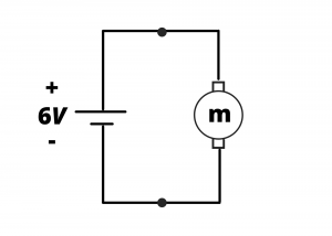
1.5 Assemble your smart car using the components from your kit. Build the circuit of figure L3.6 comprised of a 6V battery and one of the motors from your assembled car. Use the digital multimeter (DMM) to determine the current drawn by the motor (you’ll need to hold the car up in the air to do this.) How long would the battery last if the circuit were kept running? When you’re finished, connect the battery to a motor and watch the car spin in circles on the ground.
1.6 Locate the cadmium sulfide cell (CDS) from your electronics kit and measure its resistance as you change the amount of light shining on it. You may want to go back to section 2.7 to see a video of this. Section 2.7 Resistors and Ohm’s Law
Based on this characterization of the CDS cell, design, build, and test a voltage divider circuit that changes its output voltage from  when dark to
  when light shines on the CDS cell.
1.7 The voltage divider you built in exercise 1.6 can be viewed as a light-dependent variable voltage supply. Can you use this to vary the speed of your motor? Try it. (We will pursue this idea further in lab 2)
1.8 Download the Arduino IDE from this URL: https://www.arduino.cc/en/software. Make an LED blink at a rate of 10 Hz (on for 0.05 sec, off for 0.05 sec, repeat). Then repeat at a rate of 0.5 Hz.
Here is a video demonstration of this lab to help you get started.
 to as light shining on the CDS cell varies. For this and all lab submissions, be sure to have a piece of paper in the background with your name hand-written on it. This will be necessary to receive credit for your submission.
