7.5 Relaxation Oscillator
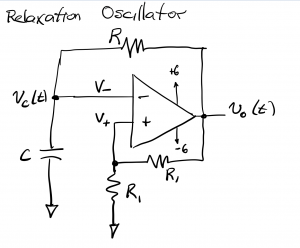
The results of the previous discussions are applied to the analysis of a relaxation oscillator below. Such an oscillator is based on an op amp provisioned with both positive and negative feedback paths and powered using a bipolar voltage supply, with +6V and -6V rails. Note that this op amp is not a negative feedback amplifier owing to the positive feedback path. Therefore, the summing point constraint does not apply (that is, we can not assume V+ = V– in the forthcoming analysis.) This circuit is analyzed as a voltage comparator, namely, vo(t)=+6V when V+ > V– and vo(t) = -6 when V+ < V–.
The following sketch plots vo (in black), V+ (in blue) and vc (in red) all as a function of time. We begin by assuming that the capacitor is initially discharged so that vc(0) = V– =0 and we assume the op amp output is at the positive rail, with vo=6V so that V+ = 3V. The capacitor, being connected to vo=6 through R, begins charging, with its voltage following the exponential curve we discussed in previous chapters, on a trajectory to exponentially approach +6 volts (red). The instant vc(t) exceeds 3V, V– becomes larger than V+, and this causes the op amp output to switch from +6 to -6V. At this point, the capacitor begins discharging, on a trajectory to exponentially approach -6 volts. Eventually, the capacitor voltage drops just below -3V, at which point V+>V– and the op amp output switches to +6 V again. The process repeats indefinitely.
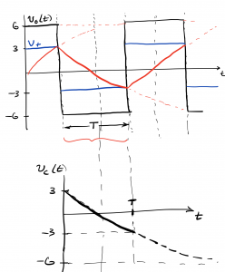
We can determine the duration of each of the positive and negative excursions of the periodic waveform by analyzing one respective segment. We consider the downward trajectory of the capacitor voltage as it transitions from +3V, exponentially approaching -6V, but stopping at -3V as described above. We use the formula developed in the previous chapter and find that the pulse duration is ` T=1.1RC seconds.

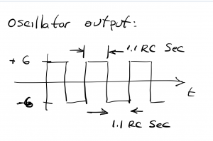
The output of the circuit, shown below, switches, or oscillates, between +6 and -6V, with 1.1RC seconds per pulse. The resulting waveform is periodic with a repetition period 2.2RC seconds, corresponding to a frequency 1/2.2RC Hz.
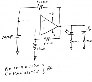
Example circuit: The following circuit shows a relaxation oscillator with two LEDs as output devices. One of the LEDs will turn on when the oscillator output is positive, while the other turns on when the oscillator output is negative. This circuit uses voltage rails of +3V and -3V and has R and C values chosen to give a frequency of ~ 1/2 Hz.
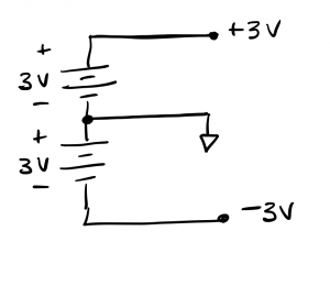
The ECE361 electronics kit is supplied with a single 6V battery pack, comprised of 4 1.5V AA batteries. That pack can be used to form a pair of bipolar 3V supplies using the schematic below. The ground wire is obtained by tapping the node in the middle of the 4 series-wired batteries.