
5.5 Lab 2 Experiments
Lab #2. LEDs and Transistor Circuits
See section 5.6 Helpful Circuit Analysis of this ebook for important supporting information about these lab exercises. Hands-on lab demos follow each circuit assignment.
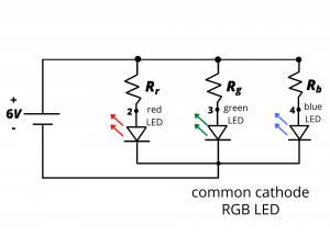
2.1 Build the following circuit using the common cathode RGB LED contained in your kit. Experiment with different colors by connecting & disconnecting the anode terminals of the diodes. It can be helpful to cover the RGB LED with a light diffuser to blend the colors. Next, connect the three resistors to GPIO output pins of your Arduino Uno. Write a program to cycle through the colors of the rainbow.
2.2 Build the following circuit which creates a detectable infra-red light beam. Detected IR light is indicated with a voltage reading on the multimeter. (Note: The schematic and hands-on videos shown below use a single 6V battery pack, and therefore the + and – voltage rails of the breadboard on the left are extended to power the breadboard on the right.

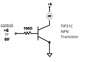
2.3 Build the following circuit which uses a low-side transistor switch to turn one of your car motors on and off depending on the value of a control voltage. (You will need to use the TIP120 power transistor for this circuit rather than the TIP31C shown.) Next, replace the control voltage with a GPIO output pin on your Arduino Uno and cause the motor to turn on and off under program control. (You’ll need to hold the car in the air while doing this unless you manage to attach the Arduino Uno to the car chassis.) Try bypassing the transistor entirely by connecting the Arduino Uno GPIO output pin directly to the car motor. Can you operate the motor this way? Why or why not?
2.4 Build the following emitter-follower circuit that controls the speed of your one of your car motors based on the light intensity shining on the CDS cell. Use the TIP120 power transistor from exercise 2.3. Your car should spin on the ground at a speed that depends on the light shining on the CDS cell. (The lower node of the 10K resistor should be ground.)

