2.10 Problems

2.1. For the circuit element shown,  volts and
  amps.
amps.
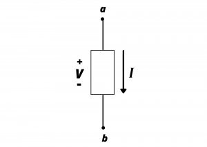
a. What is the value of  in volts? Be sure to give the correct algebraic sign.
b. What is the value of  in amps? Be sure to give the correct algebraic sign.
c. Is energy being absorbed by this circuit element, or is the element delivering energy to the rest of the circuit?
d. Over a period of 2 seconds, how much charge (in coulombs) moves through the element?
e. Which terminal, a or b, do positive charges enter?
f. What is the power absorbed by this circuit element?
g. How much energy is absorbed by this element in 1 hour?
2.2 A circuit element has voltage  volts across its terminals and current
  amps flowing through the terminals, from the
  terminal to the
  terminal as shown. Is this circuit element suppling power to the circuit or absorbing power from the circuit?

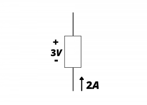
2.3 A circuit element has voltage volts across its terminals and current amps flowing through the terminals, from the terminal to the terminal as shown. Is this circuit element supplying power to the circuit or absorbing power from the circuit?
2.4 When using solderless breadboards in ECE361, the breadboards should be oriented in landscape, rather than portrait orientation (True or False)
2.5 When wiring circuits on a breadboard,
(a) what color wire should be used for connections to the + voltage rail?
(b) what color wire should be used for connections to the – or GND voltage rail?
2.6 The probes of a multimeter are inserted into an electrical wall outlet. The voltage is characterized by the expression  . When the meter is set to read DC volts, what voltage would be read? When the meter is set to read AC volts, what voltage would be read?
2.7 The probes of a multimeter are placed across the terminals of a voltage source characterized by the expression  . What DC voltage level would the meter read? What AC voltage (RMS voltage) would the meter read, assuming the multimeter has a capacitor at the AC input that blocks the DC component of the waveform.
2.8 Determine the DC voltage associated with each of the following PWM (pulse width modulation) waveforms that switch between 5V (on) and 0V (off)
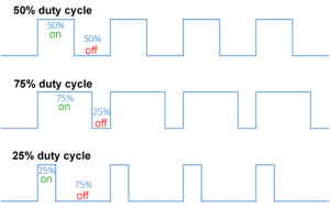
(a) 50% duty cycle DC value = _____________
(b) 75% duty cycle DC value = _____________
(c) 25% duty cycle DC value =_____________
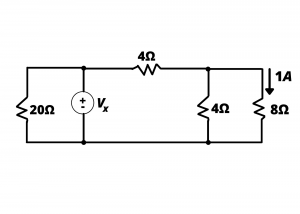
2.9 An ECE-361 student attempts to measure the current in the circuit shown but has inadvertently set the dial on the meter to a DC voltage scale. What voltage level will be read? (Hint: a voltmeter looks like a very large resistor, ideally  , or an open circuit. To solve this problem, Ohm’s law and KVL are required.)

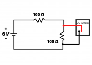
2.10 An EE student attempts to measure the voltage across the resistor in the circuit shown but has inadvertently set the dial on the meter to a DC current scale. What current will be read?(Hint: an ammeter looks like a very small resistance, ideally  , or a short circuit. To solve this problem, Ohm’s law, KCL and KVL are required.)
2.11 A  resistor has voltage
  across its terminals. What is the average power absorbed by the resistor? How much energy is absorbed over 10 seconds?
2.12 Determine the power delivered by the battery in the following circuit.
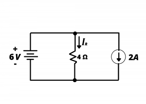
2.13 Find the current  through the resistor and then determine the power absorbed by each element in the circuit.
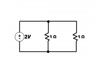
2.14. Determine the power delivered by the voltage source in the following circuit by repeated application of Ohm’s law, KCL and KVL.