
4.4 Problems
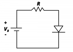
4.1 Determine an appropriate value of  so that 20mA flows through the LED in figure P4.1 if
  . Assume the diode has a turn-on voltage
  and
and  . Part (a) use the piecewise linear model; Part (b) use the simple piecewise linear model; part (C) use the ideal diode model.
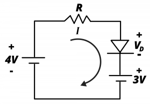
4.2 Determine the current flowing in the following circuit if  and if . Assume the diode has a turn-on voltage and
  . Part (a) use the piecewise linear model; (b) use the simple piecewise linear model; (c) use the ideal diode model

4.3 Determine an appropriate value of so that 20mA flows through the LED in the circuit of figure P4.2, above assuming the diode characterized by the following  curve
curve

4.4 In the following circuit, the input voltage is  . Assume the diode is ideal and determine the average and RMS values of the input and output waveforms (This homework problem is optional. It does not have any point value.)

4.5 Determine the current in the following circuit. Use the simple piecewise linear diode model with  for the LED.
4.6 In the following circuit with  Determine R so that the current in the circuit loop is 20 mA. Use the simple piecewise linear diode model with for each of the two light emitting diodes.

4.7 Determine the current flowing from the battery in the following circuit. Assume the diodes are ideal.

4.8 Determine the currents,  ,
,  , and
, and  for the circuit shown if and
  . Assume the LEDs have and

4.9 A digital output pin of an ATmega328P MCU on an Arduino Uno dev board can be modeled as an ideal 5V source in series with an internal 40 Ohm resistor. (a) Proper design requires that a current-limiting resistor be placed between the output pin and LED. Determine the appropriate value for such a resistor in order that the current through the LED is limited to 10 mA. (b) Determine the current that would flow through an LED connected directly to the output pin without use of a current-limiting resistor. For both (a) and (b) assume that the forward voltage drop across the LED is 2V.
