
Chapter 6. Operational Amplifiers
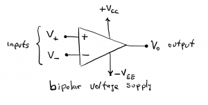
The operational amplifier, or op amp, is an active electronic device used for many applications including signal amplification, filtering, comparing voltage values, adding signals together, buffering, or isolating components of a circuit, and creating timing oscillators. Op amps are active devices, meaning that power needs to be supplied to them, in the form of unipolar or bipolar DC voltage sources, to operate. An op amp is a difference amplifier that produces an output voltage proportional to the difference between two inputs, the non-inverting input, denoted by + or  , and the inverting input, denoted by – or
  . The schematic symbol for the op amp is a triangle having two inputs and one output.

The op amp is an active electronic device constructed from dozens of transistors; the details of such construction are not of concern to us here. Instead, our interest is in using op amps for different circuit applications and we therefore need to understand how the op amp behaves when it is used as a circuit element. Op amps generally require a bipolar (one positive voltage and one negative voltage) pair of external DC voltages to operate, labeled  and
and  as shown. Note that all voltages shown in this diagram are node voltages, and they are measured relative to a common reference or ground node which is established by the power supplies, as described below.
The external voltage requirement can either be met with a unipolar power supply (such as  ,
,  =ground) or a bipolar supply (such as
  ,
,  ) as shown below. Note that ground is the negative terminal of the power supply.

It is common to draw this circuit without a connecting wire between and the – terminal of the  battery, but using ground symbols instead. Keep in mind that the two input signals, and , are each relative to ground,

In the bipolar power supply configuration, ground is the node connecting the – terminal of one power supply and the + terminal of the other supply.

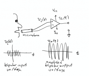
Bipolar voltage supply is used when the op amp takes AC differential input voltages and/or produces AC output voltages. An example application requiring bipolar voltage supply would be an op amp circuit that amplifies an audio signal, such as the oscillating voltage on a microphone.
An example of an application requiring unipolar voltage supply would be an op amp circuit that generates a control voltage to drive an LED on or off, based on a comparison of two input values. This example will be discussed further in this part of the book. Our applications in this course will primarily involve unipolar voltage supplies. Note that in the schematics shown on this page, the op amps are shown having five terminals or connections: the differential inputs, and , the output,  , and the power supply rails. Unipolar supply rails are often labeled
  and the ground symbol. whereas bipolar supply rails are labeled and . (Like much of the labeling in electronics, and have historic significance, referring to the positive voltage at the collector,
  , and the negative voltage at the emitter,
  , of a transistor. Such labeling conventions tend to stick around and become part of common usage.) The power supply voltages are often referred to as voltage supply rails. Schematic drawings of op amp circuits sometimes show the voltage supply rails, but not always.
Op amp saturation. Voltage rails typically range between  and
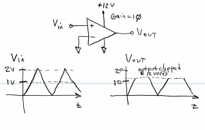
and  volts, depending on the particular op amp selected. The output voltage of an op amp is not capable of exceeding the power supply voltage. If the product of the differential input voltage and the op amp gain exceeds the voltage rail, the output voltage will be saturated, or clipped, to the rail voltage. Consider the illustration of a amplifier circuit below, which has a gain of
  (we will cover this in a subsequent section) and a unipolar supply voltage rail of
  . The inverting input is grounded and an input voltage is applied to the non-inverting input, so that the output voltage is
  . Differential input voltage levels <
  would be amplified by a voltage gain of in this circuit, while differential input levels exceeding would exhibit gain clipping or saturation, owing to the inability of the op amp to deliver an output voltage exceeding . A characteristic feature of any op amp is a very large open-loop gain,
  , which it typically
  to
to  or even higher. A consequence of this large gain is that op amps readily saturate for very small differential input signals; this occurs unless negative feedback paths are introduced to reduce the overall gain of the circuit. This is developed further the next two chapters of this part of the text.
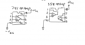
Op Amps are often supplied as dual in-line package (DIP) integrated circuits, drawings of which are shown below. Pin-out drawings of the popular 741 Op Amp (one op-amp per IC) and 358 Op Amp (two Op Amps per IC) are shown.
Note that the 741 has one op amp circuit within the IC chip, whereas the 358 op amp has two op amps on a single integrated circuit chip.
