2.3 Circuit Elements
This section explores a more complicated circuit than we saw with circuit#1, characterized by several nodes and loops, along with short circuits, series connections, resistors, and light emitting diodes (LEDs). We define all these terms below.
Circuit#2. Consider a circuit comprised of a 6V battery and a pair of resistors and LED’s with the schematic shown in fig 2.20. There are two series-connected resistor-LED circuits, each connected in parallel to a 6 V power supply.

The wiring implementation of this circuit on a solderless breadboard is shown below:

In the next chapter, we will introduce circuit laws that will enable us to calculate the voltage and current at various locations in this circuit. Ahead of that, we define a number of terms that we need to use.
Node. A node in a circuit is a point at which two or more circuit elements are joined together. The following figures show the nodes in the circuit of figs. 2.20 and 2.21:

The circuit has four nodes. These include the two nodes connecting the 1kΩ resistors to the LED’s; the top node, connecting the + terminal of the battery to the top two resistor leads, and the bottom node, connecting the – terminal of the battery to the two LED’s. The nodes are shown on the breadboard circuit below:

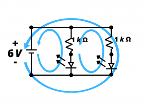
Loop. A loop in an electrical circuit is a closed path starting at at node and proceeding through circuit elements, eventually returning to the starting node. This circuit has three loops, shown below. At this point, our purpose is simply to give definition to the term “loop”. In the next chapter, we will discuss circuit analysis using loops.
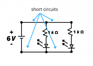
Short circuit. A short circuit is defined as a section of a circuit that has zero voltage drop between two nodes. In the next chapter, we will discuss Ohm’s law and realize that a short circuit can also be thought of as two circuit nodes with zero resistance between them. When wiring circuits using hook-up wire, we typically neglect the resistance of the wire and assume we are connecting the nodes with short circuits. The short circuits for the schematic we are discussing here are identified below:
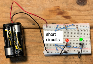
These short circuits are identified below in the breadboard implementation of the circuit. The significance of the definition of a short circuit will become more clear as we begin to look at circuit models and analysis.
Interesting observation: Clothing built with light emitting diodes (LEDs) has emerged in recent years, with functional, entertainment, and fashion applications. An engineering challenge associated with manufacturing such clothing related to the integration of LED’s, batteries, and microcontrollers into the fabric.

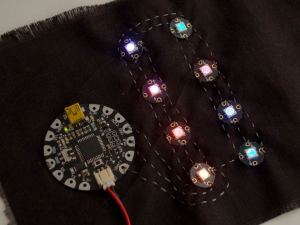
Conducting thread is used in these garments in place of wire to interconnect components. LED’s need to glow intensely in order to be seen during bright outdoor conditions, and this requires the use of fairly high currents in the circuits. The finite resistance of the interconnecting thread, multiplied by the large currents, creates voltage drops along the thread-interconnects. We will learn how to calculate these effects later, but the point is that the assumption that the thread is an effective short circuit is not necessarily valid in an application such as this.
Open circuit. An open circuit is defined as a section of a circuit through which zero current flows. An open circuit can also be thought of as two circuit nodes with infinite resistance between them.
Series circuit elements. Circuit elements connected end-to-end, with no other path for current to flow through the node joining them, are said to be in series.
Question: which elements of circuit#2 are connected in series?
Answer: the two resistors are each connected in series with an LED.
Parellel circuit elements. Two circuit elements are connected in parallel if both ends of one element are connected directly (ie, by short circuits) to the corresponding ends of the other. Referring to circuit#1 from the previous chapter, the AA battery and the resistor are connected in parallel.
Question: which elements of circuit#2 are connected in parallel?
Answer: no circuit elements satisfy the definition.
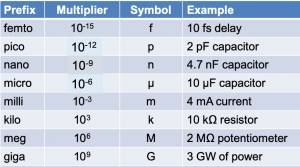
Before completing this section on circuit terminology, we list a number of important prefixes that are used commonly when dealing with electrical and electronic circuits. For example, a 1000Ω resistor is typically referred to as a 1 kΩ resistor or a 1 kiloΩ resistor. A capacitor with capacitance of 4.7E-9 F is typically referred to as a 4.7 nF or 4.7 nano-Farad capacitor.