
3.2 Voltage and Current Dividers
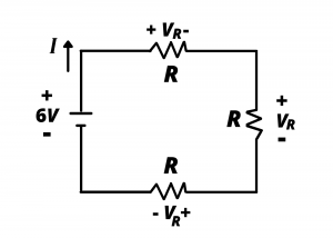
Voltage Dividers. Consider the circuit shown in figure 3.10 having three identical resistors connected in series to a  battery. What is the voltage drop across each resistor? Intuition might correctly lead the reader to the answer of
  : the battery is connected in series with three identical resistors. The battery’s must be dropped across the series set of resistors; the resistors are identical; there should be
  of or across each resistor. We can readily obtain this result by applying KVL around the circuit loop and making use of the fact that the current is the same for all elements in the series-connected circuit, hence the voltage drop across each resistor is the same. Application of KVL around the loop gives:
(1) 
which readily gives us  .
.
This is a voltage divider circuit. Recall from the previous chapter that a series-connection of three resistors each having resistance  is equivalent to a single resistor having resistance
  . In this circuit the resistance seen by the battery, that is, the equivalent resistance loading the battery, is .
Knowing this, we deduce that the current in the loop is
(2) 
Having found the current, we can determine the voltage drop across each resistor via Ohm’s law:
(3) 
Note that the resistance of each resistor is 1/3 of the total series resistance seen by the battery, and the voltage drop across each resistor is 1/3 of the battery voltage. This is the behavior of a voltage divider circuit which we will define below. We first extend the discussion to the case where the series-connected resistors have different values.
Consider the following network which has three series resistors each having a different value, and let us determine the voltages across  ,
,  , and
, and  .
.
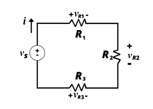
To begin, we note that the three resistors are all connected in series; this circuit is equivalent to the following circuit, in which the voltage source is applied across a single resistor having equivalent resistance
(4) 

The current in the loop is
(5) 
The current having been determined, we readily obtain the voltage across each of the resistors via Ohm’s law:
(6) 
(7) 
(8) 
We thus see that the voltage drop across each series resistor is a fraction of the source voltage; the fraction is the ratio of the series resistance to the total resistance seen by the voltage source.
Note that the sum of equations (6), (7), and (8) gives:
(9) 
Examples
Voltage Divider Example. Determine the voltages across the five resistors in the following circuit if  ,
,  , and ,
  and
and  are all
  resistors.
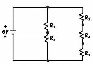
Solution: This problem can be solved by combining resistances as shown in Figure 3.13b, then forming a single equivalent resistance, determining the current from the 6V battery, and applying KVL, KCL, and Ohm’s law to arrive at the results. Using voltage division arrives at the result more quickly when we realize that there is a 6V drop across the middle of the circuit  and the right branch of the circuit (
 ). Voltage division gives the voltage across as
  . Similarly, the voltages across
  are 4V, 2V, 2V, 2V.

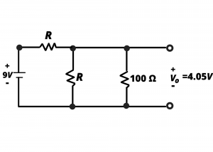
Example: A voltage divider is used to to create a  voltage supply from a
  battery by use of
  and
and  resistors as shown. Determine the output voltage when a
  load is attached to the output. Repeat for a ,
  , and
, and  loads.
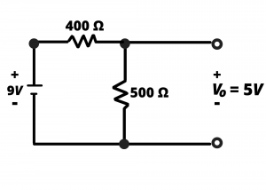
Solution: Without a load resistance, the output voltage from this voltage divider is  . When the load resistor is added to the circuit as shown in Figure 3.14b, the voltage division changes. The 9V battery voltage divides into a voltage across the resistor and the parallel combination of the resistor and the added load resistance,
  . Since this parallel combination will be less than , the output voltage will be less than in the non-loaded case.
A load in parallel with is  . The output voltage in this case will be
A load in parallel with is  . The output voltage in this case will be
A load in parallel with is  . The output voltage in this case will be
A load in parallel with is  . The output voltage in this case will be
Clearly, the effect of “loading down” the output by the addition of a parallel load resistance is to reduce the output voltage; decreasingly smaller load resistances represent increased loading, in the sense that smaller and smaller load resistances produce greater changes in the behavior of the voltage divider circuit. An infinite load resistance,  would cause no change in the voltage divider, and we would have
  . A
. A  load resistance would result in
  .
.

Example: Considering the behavior of the loaded-down voltage divider of the previous example, design a voltage divider circuit to provide an unloaded 4.5V output from a 9V input. When loaded with resistance values between 100kΩ and 100Ω, the output voltage should not drop below 10% of the desired 4.5V value.

Solution: With reference to figure 3.15a, in the unloaded case, any equal value  will divide into the required
  output voltage. We know from the previous example problem that load resistances will cause
  to decrease below 4.5V, and we know that smaller load resistances (which, in effect, represent “larger loads” owing to their larger impact on the circuit) will cause larger decreases than larger load resistances. The problem specifies that should not drop below
  %, or
%, or  so
so  should be chosen to provide a output voltage when the circuit is loaded down with a resistor. This problem thus is reduced to determining the value for the circuit shown in figure 3.15b. A value
  will result in the desired output voltage when the circuit is loaded with a resistance. The algebra is left as an exercise for the reader to show.
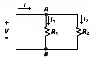
Current Dividers. Consider the circuit shown, where a current  is divided between two circuit branches, with branch resistances and .

 divides into two branches,
  and
and 
We wish to determine how current divides or separates, into currents and . We begin by noting that, via Ohm’s law,
(10) 
and
(11) 
Since we are seeking an expression giving and in terms of we need an expression relating  and . We replace the two parallel resistors by their equivalent resistance,
(12) 
from which we obtain
(13) 
Substituting eq (13) into eq (10) and (11) we find
(14) 
and
(15) 
This result shows how the current divides fractionally into the two parallel paths. We thus see that the current through each parallel resistor is a fraction of the entering current; the fraction for one resistor is the ratio of the resistance of the other resistor to the total resistance.
Examples
Example: In the following circuit,  and
and  . If a current
  flows into this network, determine the current flowing through and
Solution:  while
while  This example well illustrates the common maxim “current takes the path of least resistance”.
