
5.2 Common emitter low-side switch
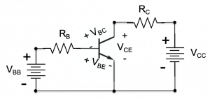
The schematic of common emitter transistor circuit is shown in figure 5.5. This circuit can be thought of as two circuits connected together by the transistor. The base circuit, on the left, comprises the base voltage source  , base resistor
  , and the base-emitter junction of the transistor, which has a forward voltage drop
  . When a transistor is on, in either the active or saturation modes, discussed below, ~
  . This “built-in” voltage corresponds to the turn-on or forward voltage drop across the semiconductor junction formed between the base and emitter and is analogous to the forward voltage we saw in a diode. The collector circuit on the right comprises voltage source
  , collector resistor
  , and the voltage drop between the transistor collector and emitter terminals,
  . We will see that this voltage drop varies between ~0V and ~ depending on the base current.
The same circuit is redrawn in figure 5.9, emphasizing node voltages and showing the base, collector, and emitter currents.
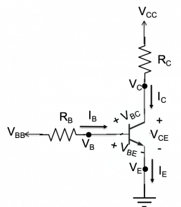
As we shall see below, and determine the base current,  into the transistor. This current, in turn, determines whether the transistor is on or off, and it consequently ends up controlling the voltage drop and the current through resistor . We will examine the use of this circuit as a “low-side switch” that, in effect, controls whether or not power is delivered to . Before exploring these details, we present a simple motivating example.
Switching a motor on and off. Consider the simple circuit comprising a small DC motor connected to a battery via a mechanical on/off switch (a single-pole, single-throw switch) shown in figure 5.7:
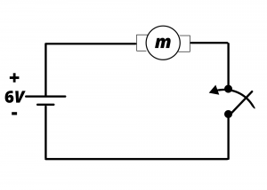
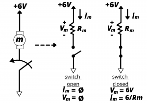
Clearly, when the switch is closed, current flows in the loop, the 6V of the battery is applied across the terminals of the motor, and the motor spins. Without any mechanical load on the spinning shaft, the motor draws ~  of current as we learned in Lab 1. Electrical power is delivered to the motor when the switch is closed; and no power is delivered to the motor when the switch is open. This circuit is redrawn in figure 5.8 to emphasize node voltages below:
We can model the motor as a resistance  , where ranges between a few ohms for a mechanically-loaded motor and perhaps ~
  for an unloaded motor. (We are not aiming to be precise here. We simply want an approximate value that we can used as an illustration.)
Open switch, motor off. The open switch behaves as an infinitely-large resistance, through which zero current flows. Therefore,
(1) 
By Ohm’s law, the voltage drop across the motor when the switch is open is
(2) 
The power delivered to the motor is
(3) 
Closed switch, motor on. The closed switch behaves as short-circuit having zero resistance. In this case, the battery voltage is dropped across the motor, and
(4) 
From Ohm’s law, the current through the motor is
(5) 
and the power delivered to the motor is simply
(6) 
We thus see that the power delivered to the motor is zero when the switch is open and 3.6 W when the switch is closed. This switch in this circuit can be considered as low-side switch that is used to connect, or disconnect (or, to “make” or “break”, respectively) the connection between the motor’s lower terminal and ground. The switch considered here is a mechanical SPDT-type, that makes or breaks electrical contact when two pieces of metal are brought together or kept apart by mechanically throwing the switch into on and off positions, respectively. Below, we consider the implementation of a low-side switch using a transistor.
Turning motor on and off via low-side BJT. We now consider the problem of switching a motor on and off using a transistor. The relevant circuit is shown in the upper left of the following figure. The motor is modeled as the resistance connected between and the collector of the transistor. The operating mode of the transistor is determined by the voltage and the base resistance . In the cutoff mode, the transistor is off and no power is delivered to the motor. In the active and saturation modes, the transistor is on, and power is delivered to the motor in each case. In the saturation mode, the transistor behaves as a low-side “on” switch, enabling power to be delivered to the motor. The active mode acts as a current amplifier and delivers power to the motor in proportion to the square of the base current; this mode should be avoided when configuring a low-side switch. Saturation is ensured by choosing a base resistor RB that results in a base current  . A “rule of thumb” design practice is to operate the base current significantly higher than this, with
  .
.
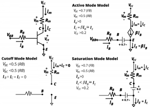
We illustrate using a numerical example in which the motor is modeled as a 10Ω resistor. The transistor’s operating mode is determined by the control voltage VBB and the base resistance RB. The transistor has a gain β=100.
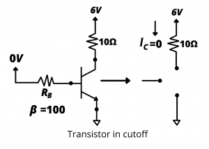
Cutoff mode. Consider the case where the control voltage VBB=0. In this case, IB=0, IC=0 and IE= 0; the transistor is off, and no power is delivered to the motor.
Active mode. Now consider the case where the control voltage VBB=6 volts and the base resistance RB = 10kΩ.
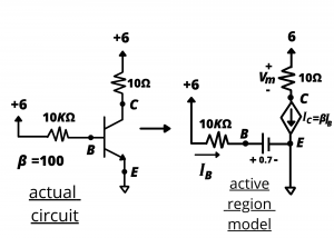
In this circuit, the active region model predicts  0.53 mA. The collector current is
  53 mA = 0.053 A. The voltage drop across the motor is
  0.53 V. The power delivered to the motor is
  or 28 mW.
Saturation mode. We now consider the case where the control voltage  volts and the base resistance is reduced to
  . This results in a significantly larger base current, which drives the transistor into saturation.
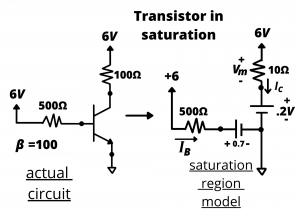
The base current in this circuit is  10.6 mA while the collector current is
  0.58A or 580 mA. We know the transistor is in saturation since
  . In this case, the design achieves IB ≈2IC/Beta, less than the design goal of 5I/beta. An important point about this circuit is that source of current flowing through the motor is directly from the 6V battery; it does not flow through the base. This is why relatively small base currents can be used to switch devices on and off even when those devices draw relatively large currents.
