
2.9 Device I-V Characteristics
This section summarizes the current vs. voltage ( ) characteristics of the devices we have discussed so far in this text. (Note that when we write in this context, this has nothing to do with subtracting
  from
from  ; rather, we are interested in a graphical plot of versus , and by convention, this is referred to as an curve or characteristic.)
Short circuit. We previously defined a short circuit as a length of wire having zero resistance and as a device that has zero voltage drop between its terminals. We usually consider short lengths of wire, such as the connecting wires in the ECE 361 kits, to be short circuits.
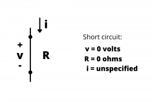
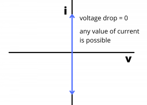
The curve for a short circuit is a vertical line plotted at  , characterized by a voltage drop of zero, and having any possible value of current. (The arrows at the end of the blue line shown in Figure 2.75 indicate that the current values can range from -∞ to ∞ for a short circuit.)
 curve for a short circuit
Open circuit. An open circuit has been characterized as a circuit element having infinite resistance between its terminals, through which zero current flows.
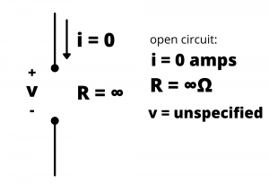
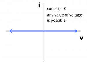
The characteristic for an open circuit is a horizontal line plotted at  with possible voltage values from -∞ to ∞ volts. Any value of voltage is possible across an open circuit.
 curve for an open circuit
SPST switch: A single-pole, single-throw switch has two positions. In the closed position, the switch behaves like a short circuit between its terminals and it exhibits the characteristic of figure 2.75. In the open position, the switch behaves like an open circuit between its terminals and it exhibits the characteristic of figure 2.77.
Examples
Example: Determine the voltage drop across the SPST switch and the current through the circuit loop in the circuits shown in figures 2.78 and 2.79.
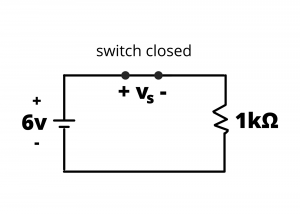
Solution: Applying KVL around the loop,  . Since
  for the closed switch, we have
  or
or  .
.
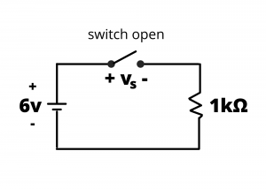
Solution: Applying KVL around the loop, since for the open switch, we have  . Many people tend to be surprised with this result. Another way to think about this circuit is to consider the switch to be a resistor having resistance
  when closed and
  when open. In the next chapter, we will introduce voltage dividers, so it might be helpful to come back and re-examine this problem after having covered that material and interpret this circuit as a voltage divider. When the switch resistance is zero, the battery voltage is all dropped across the
  resistor. When the switch resistance is infinite, all the battery voltage is dropped across the switch.
Ideal voltage source. An ideal voltage source maintains a specified voltage drop between its terminals independent of other circuit elements connected to it.
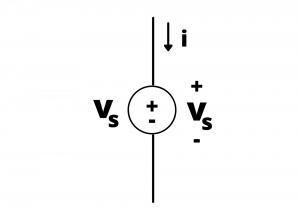
The characteristic for an ideal voltage source is a vertical line plotted at  , extending from i= -∞ to i= +∞, indicating that, theoretically, all possible values of current through the source are possible.
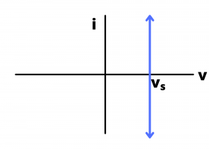 curve for a voltage source
 . We use the more general lower-case variable rather than the DC-only upper-case variable
  to allow for the possibility that the source voltage can be either a DC voltage or voltage that varies with time. In this case that varies with time, then the value shown in figure 2.81 would represent the instantaneous value of
  at a particular point in time.
Ideal current source. An ideal current source maintains a specified value of current through its terminals independent of the voltage drop across its terminals and independent of anything else connected to it.
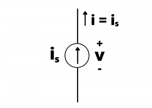
The characteristic for an ideal current source is a horizontal line plotted at  , extending from
  to
to  , indicating that, theoretically, all possible values of current through the source are possible.
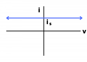 curve for an ideal independent current source
Resistor. The characteristic for a resistor, specified by Ohm’s law, includes all possible values of voltage and current that satisfy the relationship  .
.
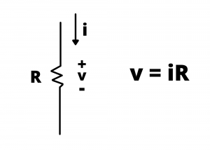
The characteristic is a straight line through the origin having slope  .
.
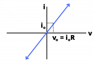 curve for a resistor
Diode. All devices discussed so far are linear devices characterized by linear relationships. The semiconductor diode is a non-linear diode characterized by a non-linear characteristic shown below. We discuss diodes in chapter four.
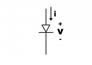
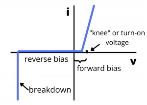 curve for a semiconductor diode