
3.3 Node voltages
Up to this point, the voltages we have considered have been voltages across circuit elements, meaning the difference in voltage between the two terminal ends of a circuit element. We now consider node voltages, which represent the voltage at nodes in a circuit. As we shall see, we are primarily interested in the difference between two node voltages, and one of the node voltages will frequently, but not always, be considered a reference or “ground” node.
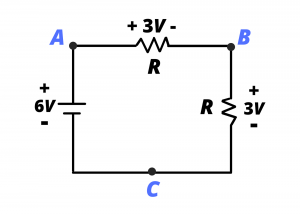
Consider the simple voltage divider circuit shown below, where a pair of identical resistors is used to divide the voltage of a  battery into two
  drops in series. The three nodes in this circuit are labeled
  ,
,  , and
, and  . We now consider the voltages associated with these nodes.
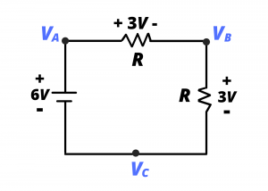
The circuit is re-drawn in figure 3.18, below. Instead of labeling the nodes , , and , we define voltage variables  ,
,  and
and  at the three nodes. Individual voltages such as are meaningless by themselves, but the voltage differences,
  and
and  are meaningful and useful quantities.
to height , the difference in gravitational potential at the two heights, multiplied by the mass of the book, tells us how much energy we need to lift the book. Knowing the gravitational potential at height , by itself, does not tell us about energy transfer.
Back to the circuit:
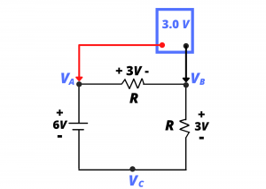
Consider in figure 3.18. We can see from examining the circuit that this is simply the voltage across the horizontal resistor, and it is, therefore, 3 V. Indeed, if we were to attach the leads of a DC voltmeter between nodes labeled and as shown, the meter would read , indicating that node voltage is higher than node voltage . (To further develop the notion that a node voltage, by itself, is meaningless, consider attaching the red probe of the voltmeter to without attaching the black probe to anything in the circuit.)
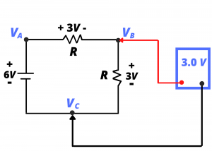
Let us now consider the voltage between and and its measurement using the voltmeter as shown. Likewise, this measurement would read .
Very often we specifically identify one of nodes in a circuit as the ground node or the reference node. When this is done, it is understood that node voltages are measured, or interpreted, relative to this reference node. Consider the same circuit redrawn, where we re-label node as a ground node:
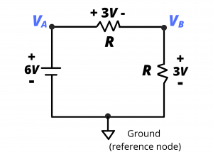
When this node has been so defined, it is understood that node voltages and are measured or calculated relative to this reference node. Thus, the black probe of the voltmeter would be placed at the ground node and the red probe would be placed at or to measure the node voltages.
Examples
Example: Determine the current  through resistor
  in the following circuit if node voltages are
  and
and  and
and  .
.
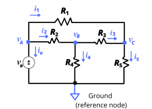
Solution: Since the know the voltages at the two ends of , we can use Ohm’s law to find the current through this resistor. Thus,  .
.
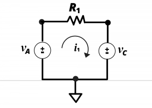
To help clarify how this result is obtained with knowledge of node voltages  and
and  , consider the following circuit which shows resistor connected between the + terminals of independent sources having voltages and . This is an equivalent representation of the resistor having end-point node voltages and . Applying KVL around the loop gives:
  from which we obtain
Example: Determine the voltages , , and in the circuit shown.
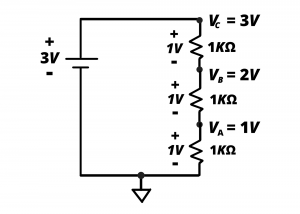
Solution: We are interested in the node voltages relative to the ground node shown. Node is connected (or tied) to the + terminal of the  battery and the – terminal is tied to ground. Therefore, = 3 V. We recognize the circuit as a voltage divider where the 3V from the battery is divided equally into 3 1-volt drops in series. Since the lowest 1kΩ resistor has a 1 V drop, we know that is 1 V. Since the lowest two resistors each have a 1 V drop, we know that is 2 V.
