
5.3 Emitter follower
Motivating example: motor loading down the voltage divider formed between the CDS cell and a 10k resistor.
Active mode Emitter Follower. We now consider an emitter follower circuit which makes uses of the active mode of a transistor to produce a variable voltage across a motor, while pulling current directly from a battery. In this circuit, the motor, represented by resistor Rm, is connected between the emitter of the transistor and ground while the base is connected to a voltage source that varies between 0 and 6V. The BE junction is forward-biased in this circuit while the BC junction is reverse biased, and the transistor is in the active mode with equivalent circuit shown below, right.
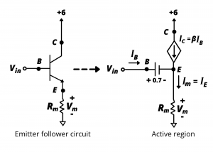
The voltage drop across the motor, Vm, is 0.7V below Vin. Whether the input voltage is increased or decreased, Vm = Vin – 0.7, and the motor voltage is therefore said to follow Vm. The current supplied to the motor comes from the collector, having been sourced directly from the battery. This circuit, therefore, provides a variable motor control voltage, Vm, while sourcing current from the battery. A variation of this motor speed control circuit is assigned in lab exercise 3.3.
