
3.5 Thevenin Equivalence
A circuit comprised of resistors and independent voltage and current sources can be substituted for its Thévenin equivalent circuit. Such a substitution can be helpful in circuit analysis as well as in circuit implementation. The Thévenin equivalent circuit is constructed from an ideal independent voltage source connected in series with a resistor as shown:
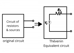
Pause and think about this for a minute: any circuit comprised of resistors and sources can be substituted for another circuit comprised of a voltage source in series with a resistor. The value of the voltage source and the resistor depend on the particulars of the original circuit, but the Thévenin circuit and the original circuit are equivalent to each other from the point of view of their respective output terminals. Each circuit could be enclosed within a box that obscures or hides the insides with only the pair of output terminals exposed, and one would not be able to tell the circuits apart by making measurements at the output terminals. They are equivalent.
The schematic diagram for the Thévenin equivalent circuit is an ideal independent voltage source of voltage  volts in series with a resistor having resistance
  (in both cases, the subscript
  represents Thévenin voltage or resistance.) Later in this chapter, we describe an approach for determining these values. First we introduce an example to illustrate the utility of such a circuit.
Equivalent circuit for a real battery. Up until now, we have modeled batteries as ideal independent voltage sources. Recall that an ideal independent voltage source maintains a specified voltage between its terminals independent of anything connected to it. We know from experience that batteries can get warm and their voltage can drop, especially when they are loaded with small resistances that draw large currents. We can model a real battery as an ideal battery in series with a resistor. Modeling a real battery this way predicts some important behaviors, and this is a good illustration of the use of a Thévenin-type circuit.

Consider a 12V automobile battery. Such batteries typically have a small, but non-negligible internal resistance of ~ 0.05Ω. The equivalent circuit for such a battery is simply an ideal 12 battery in series with this small resistance, as shown in figure 3.37:

Such batteries are used to power many devices in a car, including the starter, the headlamps, radio, computer, etc… We will examine the impact of the internal resistance on these devices using the circuit shown in figure 3.38, which treats all devices attached to the battery (ie, starter, radio, computer, etc…) as a single load resistor  that has an associated load current,
  . We are interested in determining the actual voltage that would applied to the headlamps and other devices in the car when powered by a 12V battery. What do you think the voltage will be?

Applying KVL around the circuit loop allows the load voltage to be determined:
(1) 
or
(2) 
Equation (2) simply states that the voltage delivered to the load is 12V minus the voltage dropped across the internal battery resistance. This dropped voltage is the small internal resistance of the battery multiplied by the current pulled by the load resistance.
Assume that the load is simply the headlight circuit in the car, having a load resistance such that the load current = 10 A. Inserting this current into equation (2) results in a load voltage delivered to the headlights of 12 – 0.05(10) = 11.5 V.
Now consider what happens when the engine starter is engaged at the same time that the headlamps are on. Figure 3.39 shows the two parallel loads, one corresponding to the starter (100A) and the other corresponding to the headlamps (10A).
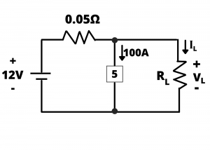
The combined load current in this case is 110A and eq (2) results in a load voltage delivered to the headlights of 12 – 0.05(110) = 6.5 V. This is a commonly encountered scenario, in which automobile headlamps are switched on, and the starter is operated momentarily as the car engine is started. The voltage level initially applied to the headlamps is 11.5V, causing a bright glow; the voltage then decreases to 6.5V while the starter is engaged, resulting in a dimming or decreased lamp brightness, followed by a return to bright lights when the starter is released and the voltage returns to 11.5V. Power is dissipated within the internal resistance of the battery while this is happening, causing the battery to heat up.
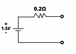
The equivalent circuit for a 1.5V AA battery is shown in figure 3.40, where in this case the internal resistance is 0.2 Ω. This resistance is four times as large as the internal resistance of a car battery because different, less expensive material is used to create the anode and cathode electrodes. AA batteries are not used in circuits that attempt to draw more than a few amps of current.
A 9V battery has an internal resistance of ~ 2Ω. Such a battery is made from 6 AAAA batteries. (Such batteries exist, although they are not too common. There are AA batteries, smaller AAA batteries, and even smaller AAAA batteries). Inside a 9 V battery are 6 AAAA batteries wired in series. Each has an internal resistance of ~ 0.3Ω so that the combined resistance is ~ 1.8 – 2.0 Ω. A load that attempts to draw 1A from a 9V battery will only see a load voltage of 7V as a result of this internal resistance. Owing to this relatively high internal resistance, 9V batteries are typically used with only 10s of mA or less, while AA batteries can be used in circuits drawing up to an amp or more. Here is a link to a 9V battery data sheet.
Energizer 9 V battery data sheet
Determining the Thévenin equivalent circuit. A Thévenin equivalent circuit is constructed by analyzing (or perhaps measuring, if feasible) the original circuit, from its two output terminals, in such a way as to determine the values and  appropriate for the equivalent circuit.
Determining : In the equivalent circuit below, the open-circuit voltage,  (that is, the voltage with infinite load resistance, which results in zero load current) is equal to , therefore, knowledge of the open-circuit voltage gives us the sought-after value for the original circuit. (It is straightforward to show that = in this circuit. Simply apply KVL to the loop and let
  =0, which is the open-circuited case.)

Determining : Having determined we can determine by short-circuiting the output terminals, as shown:

Application of KVL and Ohm’s law in this circuit results in  .
.
We thus see that, for the Thévenin equivalent circuit, we can determine simply by determining the open circuited terminal voltage, . Once this is obtained, we can determine simply by determining the short circuited terminal current,  and using the expression: . We apply this same analysis to the original, equivalent, circuit, and the results give us the Thevenin equivalent circuit.
Examples
Example: Determine the Thévenin equivalent circuit for the network shown:

Solution: We first determine the open-circuited terminal voltage, :

We can determine via voltage division:  . This is for the Thévenin equivalent circuit.
We next determine the short circuited current, :
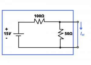
We determine by first noting that the effect of the short circuit is to short-out the 50Ω resistor. Another way to view this is to recognize that the short circuit is a 0Ω resistor; this resistor, in parallel with a 50Ω resistor, is 0Ω. The resulting circuit is simply a circuit containing a 15V battery and 100Ω resistor. is determined by applying KVL:  from which = 0.15A.

Knowing and , the Thévenin resistance is obtained via  . The original circuit and its Thevenin equivalent circuit are shown below:

