
3.1 Equivalent Resistance
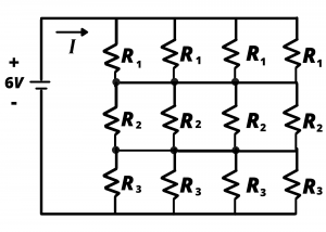
Consider the circuit of figure 3.1 which has 12 resistors and a battery, and contemplate the effort involved in analyzing this circuit. (Recall that “analyze a circuit” usually means determining the currents and voltages associated with all circuit elements.) The circuit has 13 elements so there are 26 voltage and current variables involved. The battery voltage is given, so there are 25 unknowns. Suppose our analysis goal was simply to determine the current,  , drawn from the battery. Repeated application of KVL, KCL, and Ohm’s law, applied with a degree of trial and error, and a good deal of patience, would ultimately lead to . In this section, we consider techniques for replacing resistive networks with simpler equivalent resistances. We will show that the 12 resistors shown below can be replaced with a single resistor having value
  , from which the current, , can be readily obtained via Ohm’s law.
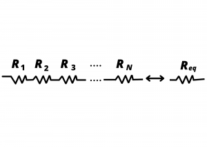
Resistors in series. Consider the series combination of  resistors shown in fig. 3.2. We want to determine the value of the single resistor
  that is equivalent to this series combination, in the sense that the series combination and each have the same
  relationship ,
  , as indicated in fig. 3.3.
 (right) such that both have the same resistance
 relationship
The relationship of the series combination is found by applying KVL to the loop in the left-most circuit of fig. 3.3, and noting that the same current  flows through all series resistors,
  . Thus,
(1) 
from which we find the relationship,
(2) 
.
For the equivalent circuit on the right side of fig. 3.3, we can write the expression by immediate application of Ohm’s law, namely,
(3) 
The two relationships of equations (2) and (3) are equivalent if
(4) 
and we see that the series combination of resistors is equivalent to a single resistor having resistance equal to the sum of the individual resistances.
The take-away point is that in any circuit, we are free to replace any series combination of resistors with an equivalent resistor equal to the sum of the series resistances, without impacting the circuit.
Examples
Determine the equivalent resistance for a series connection of five  resistors shown in fig. 3.4.
Solution: The single  resistor on the right side of fig. 3.4 has a resistance equivalent to the five series-connected resistors.
 resistors connected in series are equivalent to a single resistors
Resistors absorb energy and consequently they are limited in the amount of power they can handle without potentially heating up causing thermal problems in a circuit. Resistors are rated to handle a certain amount of power, and  ,
,  , and
, and  rated resistors are common. The resistors in the ECE361 kits are all rated at . Although the two circuits shown in fig. 3.4 are electrically equivalent, the circuit on the left can handle more power, and hence higher voltage and current, than the circuit on the right, as we explore in the following example:
Examples
Determine maximum voltage for the two circuits shown fig. 3.4 if all the resistors are rated at a maximum power of .
Solution: Consider the resistor. The maximum power and voltage are obtain via:  from which we obtain
  volts. Now consider the circuit on the left of fig. 3.4. Each of the resistors can drop a maximum voltage of
  corresponding to
  . So the circuit comprised of
  resistors can operate with up to
  volts without overheating, whereas the circuit comprised of the single resistor can only operate up to
  volts without overheating. This should make sense when we consider that resistors in series have times the mass and surface area, and hence
  the heat carrying capacity as a single resistor. If overheating is a concern, then use of a larger power-handling capacity resistor would be appropriate.
Resistors in parallel. We now consider the resistance equivalent to a parallel connection of N resistors. Proceeding analogous to the case for series resistors, we seek to obtain the relationships for the two circuits depicted in fig. 3.5 below. We begin by applying KCL at the top node of the circuit on the left, obtaining
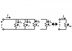
(5) 
.
Since the resistors are all connected in parallel, they all have the same voltage drop across their terminals,  . Therefore, we can re-write the KCL equation using Ohm’s law for each resistor:
(6) 
from which we obtain
(7) ![\begin{equation*} v = i [ \frac{1} {\frac{1}{R_1}+\frac{1}{R_2}+...+\frac{1}{R_N} } ] \end{equation*}](http://openbooks.library.umass.edu/funee/wp-content/ql-cache/quicklatex.com-6969a7dcd4ac0a4099021d45b2a224fc_l3.png "Rendered by QuickLaTeX.com")
For the equivalent circuit we have
(8) 
and by equating equations (7) and (8) we have the equivalence relationship
(9) 
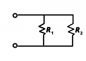
Two resistors in parallel. A simplified version of eq (9) is obtained for two resistors in parallel:
(10) 
multiplying numerator and denominator by  we have
(11) 
which simplifies to
(12) 
for the special case where  we find that
Examples
Exercise: Determine the equivalent resistance of the circuit comprised of two parallel resistors when  and (a)
  , (b)
, (b)  , (c)
, (c) 
Solution:
(a) since  , we have
  .
.
(b) 
(c) 
Exercise: Which resistors are in series? Which are in parallel? Determine the equivalent resistance of the network.

Solution:  and
and  are in parallel. The parallel combination of and is in series with
  . The equivalent resistance of the network of resistors is
  .
.
Exercise: Determine the equivalent resistance of the circuit shown if all resistances have a value of
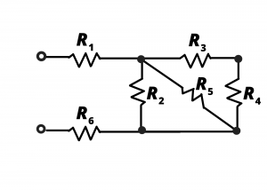
Solution: We begin by noting that and  are in series and the series combination of these two resistors is in parallel with
  and . This can be seen more clearly when the circuit is re-drawn in fig. 3.8b.
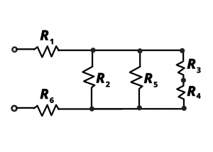
Figure 3.8c shows a simplified circuit when resistors  are combined. A shorthand notation is used to depict being in parallel with and with the series combination
  .
.
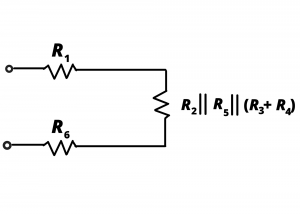
Using the value of for each resistor, the series combination  . This resistance, in parallel with gives
  . This resistance, in parallel with gives
  . Finally, the series combination of
  with and
  gives an equivalent resistance
Exercise. Determine the equivalent resistance of the circuit shown if each resistor is  .
.

Solution: We first re-draw the circuit in figure 3.9b to illustrate that and are in parallel. Likewise, and are in parallel. The combined resistance is 

