
2.7 Resistors and Ohm’s Law
Resistor. Resistors are circuit elements designed to impede the flow of current by absorbing energy and, hence, decreasing voltage across their terminals. They are used in circuits to limit current, to divide voltages into fractional parts, to “pull up” and “pull down” input values (to be discussed in a subsequent chapter), to establish timing in conjunction with capacitors and other applications. A resistor has a voltage drop, or voltage decrease, across its terminals proportional to the current flowing between the terminals. Ohm’s law stipulates that the voltage drop across and current through a resistor are related by
(1) 
or, by trivial algebraic manipulation,
(2) 
where  is the resistance having units of
  or Ohms,
  .
.

 for a resistor
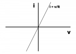
This current vs. voltage relationship (also referred to as an  relationship) defined by equations (1) and (2) can be plotted on
  and
and  axes as shown. The linear relationship between current and voltage holds for all values of and , meaning that resistor is a linear circuit element.
Note that for a resistor, the voltage drops, or decreases, in the direction of positive current flow; that is, positive charges, when moving through a resistor in the direction of the voltage drop, are giving up energy. The energy gets converted to heat in the resistor at a rate of
(3) 
which is the power absorbed by the resistor, in Watts. Equation (5) can be re-written, using equations (1) and (2)
(4) 
and
(5) 
which are two additional equations for determining the power absorbed by a resistor.
Examples
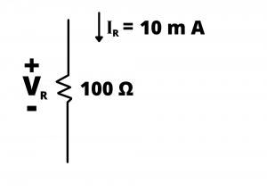
Determine voltage drop  and the power dissipated in the resistor in the circuit shown in Figure 2.60
Solution: Ohm’s law specifies that  volt.
volt.
The power dissipated in the resistor is  watt.
watt.
Determine the voltage drop across the resistor shown
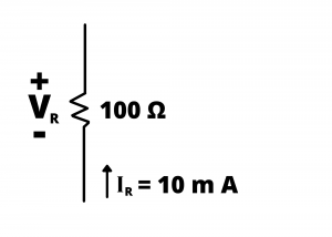
Solution: Here, we need to pay attention to the direction of the current relative to the voltage drop. Ohm’s law specifies that  when the current,
  , enters the positive polarity of the voltage drop,
  . In this problem, the voltage drop will be
  in the direction of the current. In other words, the
  voltage drop will have its positive polarity where the current enters the resistor. Therefore,
  .
.
Determine the voltage drop across the resistor in the circuit shown when the AC current given by 

Solution: Ohm’s law is valid for DC, AC, and combined AC and DC waveforms. In this case, 
Note that in the these example problems, upper case variables were used for DC voltages and currents, whole lower-case variables were used for AC voltages and currents. Note also that the time dependence for AC variables is often suppressed when drawing circuits.
Resistor values. Resistors are manufactured with standard resistance values from 1Ω to 10M Ω and they can readily purchased with tolerance values of 10%, 5%, and 1%. Different tolerance values can be purchased along with different power-handling capacities. Resistors have color bands on them that allow their resistance value to be determined via color code charts such as that shown in Figure 2.63. Some resistors have four color bands, three for determining the resistance value and a fourth specifying the tolerance. For example, a resistor having brown, black, yellow, and gold bands would have a value of 10×103Ω, or 10kΩ, with a tolerance of plus or minus 5%. Some resistors actually have five bands, three for determining resistance and a fifth for tolerance. The resistors in the ECE-361 kits are four band resistors.

The following link, from the Adafruit web site, describes the color code for reading resistor values and discusses how to measure resistance using a digital multimeter.
Resistor color code and measurement using multimeters
Examples
Determine the resistance values for the three different resistors chosen from an ECE-361 electronics kit, shown below.

Solution: The left-most resistor is color-coded brown-black-orange-gold (corresponding to the  and
and  digits, the multiplier, and the tolerance). From figure 2.63, these colors correspond to a resistance
  . A resistor with these color bands would have a resistance in the range from
  to
to  .
.
The resistor in the center has colors brown-black-red-gold corresponding to  or
or  . The resistance would be in the range from
  to
to  or
or  .
.
The resistor on the right has colors brown-black-brown-gold corresponding to  or
or  . The resistance would be in the range from
  to
to  .
.
The resistors in ECE361 kits are capable of handling power levels of  W without overheating. For some circuits, physically larger resistors are needed for handling higher power levels than this.
The actual values of the resistors shown in Figure 2.64a are  ,
,  , and
, and  as measured using the resistance measurement on the digital multimeter (DMM) from an ECE-361 kit. A photo of the measurement of the
  resistor is shown below.
 resistor in this measurement has an actual resistance of
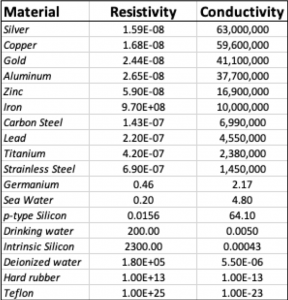
Electrical conductivity and resistivity. The electrical conductivity is an intrinsic property of a material that characterizes its ability to conduct current in response to an applied voltage. Metals, having large numbers of free electrons, have high conductivity, while non-metals, such as rubber and teflon, have low conductivity. The following table list the conductivity, having units of  or
or  . The table also lists the resistivity, which the the reciprocal of conductivity, having units of
  . At the top of the list, are the metallic conductors having high conductivity and low resistivity due to the presence of valence electrons (free electrons) in the atomic lattice of the material. The materials having the highest conductivity are silver, copper, gold, and aluminum. Copper and aluminum, because of their high conductivity and relative low cost, compared to gold and silver, are the materials primarily used for conducting wire and cables. In the lower-middle and bottom of the curve are the semiconductors, such as Germanium and Silicon and insulators, such as hard rubber and teflon. Insulators are characterized by very low conductivity, and hence very high resistivity, owing to the electrons being tightly bound to the atoms in the material’s atomic lattice. Semiconductors have conductivity and resistivity values between those of conductors and insulators; these properties can be significantly altered by adding impurities to semiconductor materials, and this phenomenon is exploited to create electronic devices such as diodes and transistors.
 ) and conductivity (
 of different materials
Conducting wire. Hookup wire, having finite conductivity and hence non-zero resistivity, has resistance, usually small, but needs to be taken into consideration in circuits that have currents of several amps or more. Wire is cylindrical with a circular cross section as shown in figure 2.66.

The resistance of a length of conducting wire can be determined by multiplying the resistivity of the wire material () by the wire length ( ) and dividing by the cross sectional area of the wire (
 ):
):
(6) 
for wire having circular cross section and diameter D, the resistance of a length of wire L and resistivity ρ is given by
(7) 
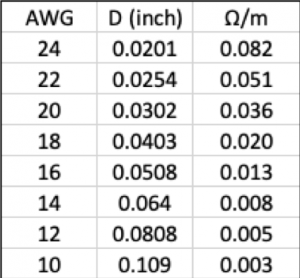
Conducting wire is specified by gauge (AWG) and material. Household wiring is usually made of copper and AWG 10, 12, or 14 is used, depending on the current of the circuit. Wire in circuits used in this class is AWG #24. The following table shows the gauge and resistance of several different gauges of copper wire along with the resistance per meter:
Other resistors:
A potentiometer is a variable resistor. These are typically 3 terminal devices, with fixed resistance between two end terminals and variable resistance between the middle terminal and the two ends.

A potentiometer trimmer is often used to adjust the resistance of a potentiometer. Your ECE361 kit contains several potentiometers as well as trimmer tool. Here is a thrilling video showing a  potentiometer being adjusted from
  down to ~
  using a trimmer tool.
A Cadmium Sulfide Cell (CDS Cell) is a two terminal device having resistance inversely related to the intensity of the light falling on its surface. For the CDS cells used in ECE361 kits, the resistance exceeds  when dark, decreases to a few
  when in the presence of ambient room light and decreases to ~
  in the presence of very bright light as shown in the following video.
A thermistor is a resistor with a resistance that varies with temperature. Your kit contains a thermistor that has a negative temperature dependance, that is, the resistance decreases with increasing temperature.
Examples
Example Problem: Determine the voltage, current, and power absorbed by each element in Figure 2.67.
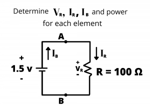
Solution: The battery voltage of  is given. Since the battery and resistor are in parallel,
  . (If we forgot that voltages in parallel have the same voltage, we could have alternatively determined by applying KVL around the circuit loop, thus:
  or
or  ) By Ohm’s law,
  or
or  . The power absorbed by the resistor is
  or
or  . (Since the positive current flows in the direction of the resistor’s voltage drop, we know that charges are giving up energy as they move through the resistor, and therefore the resistor is absorbing power.) Moving onto the battery, by KCL at node A, we have
  . Therefore, the current drawn from the battery
  , and the battery power is
  or . We know the battery is supplying power because positive current is entering the battery’s – terminal and exiting the battery’s + terminal. Therefore, we would say that the battery is absorbing
  of power.
(We might be tempted to conclude that the battery is supplying power simply because it is a battery, but this can lead to errors. For example, suppose we replaced the resistor with circuitry that caused a current to flow counter-clockwise in the loop (ie, into the + terminal and out of the – terminal of the  V battery. We would then have a circuit in which the battery is being “charged” by the circuit, in which case, the battery would be absorbing power. Before you are tempted to do this, keep in mind that primary or “disposable” batteries are not designed to be recharged and that battery charging circuits are deliberately made with elements to control the amount and direction of current flow.)
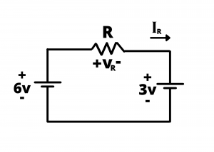
Example: Determine the current  in the circuit shown for cases when
  and
and  . What happens if
  ?
?
Solution: Applying KVL around the loop we have  or
or  volts. By Ohm’s law,
  , so
, so  or 3 mA when and
  when . When
  we have
  . implies that the resistor is replaced by a short circuit, and in our circuit model, we have a circuit in which an ideal
  battery is in parallel with an ideal
  battery. Such a circuit violates KVL and indicates how the ideal voltage source model fails when it is associated with infinite current. In practice, batteries have small internal resistance, as we will learn in the next part of this text. A battery comprised of 4 AA batteries connected in series has an internal resistance of ~
  , while a 3 V battery has an internal resistance of ~
  , and the parallel wiring of two practical batteries would result in a current of several amps, which is sufficient to cause the batteries to heat up. )
Example Problem: Determine an appropriate value for the resistor in the circuit shown so that the current through the LED is  . The voltage drop across the LED corresponding to this forward current is
  .
.
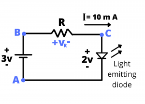
Solution: The resistor R sets the current in this circuit, with  . Applying KVL around the loop, we have:
  or
or  volt. Therefore,
  .
.
