9.3 Arduino Uno Development Board
We will confine our study to the ATmega328P MCU on the Arduino Uno development board, shown below:
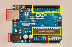
The yellow box on the right side of the board just below center is the ATmega328P MCU integrated circuit. General purpose Input/Output (GPIO) pins on the IC are connected to header sockets at the top and bottom edges of the board shown in yellow boxes.
The red box in the upper left is the USB type B socket that connects with a host computer’s USB port using an appropriate cable. When connected, this socket powers the board and facilitates downloading code from the host computer to the MCU on the board.
When not connected to a host computer, the board can be powered via the barrel-jack connector, shown in the red box at lower left, or via the Vin and GND pins, shown in the red box at the bottom edge, right of center. Here are some of the features of the Arduino Uno board:
- Microcontroller: ATmega328P, 8-bit, 32K Flash ROM
- 14 digital input/output pins (6 with PWM capability)
- 6 analog input pins
- USB type B connection
- Barrel power jack
- Vin pin (6-20 V)
- ICSP header
- reset button
- DC current per I/O pin: 40 mA
- Dimensions: 6.9 cm x 5/3 cm; 25 gram
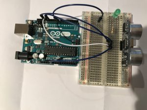
An Arduino Uno configured to control a small SONAR sensor is shown below. This system detects the presence of obstacles and activates a green LED whenever an obstacle closer than 1 m crosses in front of the SONAR. The SONAR connects to the Arduino UNO using two digital pins, an output pin and an input pin. 5V power and ground for the SONAR are also provided by 2 wires from the Arduino.
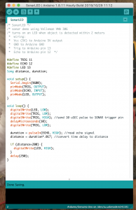
The software script that runs this system is shown below: