9.2 Embedded Design Tools
Development of an embedded control system involves selecting an MCU, designing and testing the circuitry and control software appropriate for the selected MCU, prototyping the system, then implementing the design as a professional product. The final product typically involves a creating a custom printed circuit board (PBC) on which the MCU and other electronics are soldered. The PCB along with power supply, and perhaps interfaces to other parts of a larger system, are then installed in suitable packaging that enables the system to function in its intended environment, such as within an automobile or home, or outside in rain, snow, heat, dust, and other external environmental conditions.
The ATmega328 integrated circuit (IC) is an example of a low power MCU. This IC is manufactured in several different packages; the 28-pin dual in-line package (DIP) version and its functional block diagram are shown below.
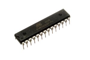
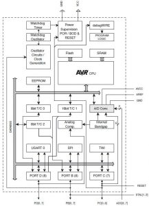
We shall not concern ourselves with the insides of this chip but will focus, instead, on the pins and their functions. The chip has the following key features:
- 32K bytes in-system re-programmable Flash memory
- 23 general purpose input/output (GPIO) pins, 6 of which can provide pulse-width modulation (PWM) outputs
- 6 channel, 10-bit analog to digital converter (ADC)
These features indicate that the chip has numerous pins that be configured as digital (high or low) input or outputs for sensing or control. The chip also has an internal analog-to-digital converter that can used for reading analog input voltages.
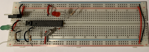
Programming this chip is usually accomplished by writing a C program, cross-compiling this program into a low level sequence of binary instructions that can be interpreted by the MCU, and then “burning” or uploading the resulting instructions into the flash memory of the device. Once it has been programmed, the chip is placed into a circuit containing power, a timing oscillator, a reset switch, and indicator LED’s, as shown below implemented on a solder-less breadboard.
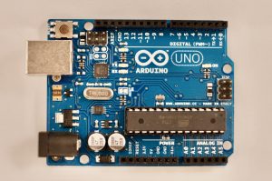
Development boards for learning, making, and prototyping. Prototyping often involves the use of a development board that provides access to the input, output and functions of the MCU while at the same time providing power and a set of useful interfaces to a host computer and test peripherals. The Arduino Uno Development board is representative of a new class of MCU development boards specifically developed to ease the process of embedded system design.
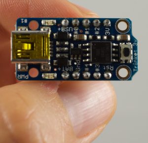
Photograph of the Adafruit Trinket microcontroller board. The on-board microcontroller is the ATtiny85 which has 8K of flash memory, 512 byte of SRAM and 512 bytes of EEPROM. This board is an example of a microcontroller development board produced for the making community.
Integrated Development Environments
Chip manufacturer microchip provides two integrated development environment (IDE) software packages, ATMEL studio
https://www.microchip.com/mplab/avr-support/atmel-studio-7
which works on Windows platforms and MPLab-X, which works on Windows, Linux, and MAC operating systems
https://www.microchip.com/mplab/mplab-x-ide
These IDE systems have a substantial learning curves associated with them but they enable embedded system designers to come up with a wide variety of design options.
The Arduino IDE has emerged as a light-weight, easy to use system for programming a set of development boards.
https://www.arduino.cc/en/Main/Software

