6.1 Ideal Op Amp Characteristics
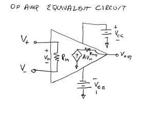
The equivalent circuit for an op amp is shown below. The two input terminals are internally connected via an input resistance, ![]() . A dependent voltage source having value
. A dependent voltage source having value ![]() provides the output voltage through the series resistance
provides the output voltage through the series resistance ![]() .
.

The input resistance of the op amp, ![]() , is typically very large, on the order of
, is typically very large, on the order of ![]() , while the output resistance,
, while the output resistance, ![]() , is typically very small, on the order of Ω. In the ideal op amp model, the input resistance is considered to be infinite, meaning there is an open circuit between the input terminals
, is typically very small, on the order of Ω. In the ideal op amp model, the input resistance is considered to be infinite, meaning there is an open circuit between the input terminals ![]() and
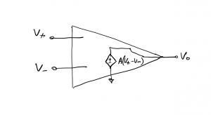
and ![]() V+ and V–. In the ideal model, the output resistance is treated as 0Ω and is treated as a short circuit. The equivalent circuit with these two idealizations is shown below. In this schematic representation, we have omitted the power supply voltage and ground, as it common in circuit drawings of op amps.
V+ and V–. In the ideal model, the output resistance is treated as 0Ω and is treated as a short circuit. The equivalent circuit with these two idealizations is shown below. In this schematic representation, we have omitted the power supply voltage and ground, as it common in circuit drawings of op amps.

Question: where else have we routinely considered the input resistance as infinite (treat as an open circuit) and ignored the output resistance (treat as a short circuit)?
Answer: voltage and current measurements made with a digital multimeter (DMM) are based on these same assumptions. When we hook the probes of a multimeter across a device to measure its voltage, we are actually “loading down” the device by placing the DMM in parallel with it. The input resistance of a DMM is on the order of MΩ, so its impact on the test circuit is usually negligible. Put another way, the input resistance of the DMM is large enough that the DMM circuit will only draw μA from the test circuit when small voltages are being measured. Similarly, when a circuit is closed with a DMM to measure current, we assume the DMM will not drop voltage. This is usually a valid assumption since the series resistance of a DMM, when used in current-measuring mode, is typically very small.
In the circuits we analyze in this text, we will assume we are working with an ideal op amp, with ![]() ,
, ![]() , and
, and ![]() , unless stated otherwise.
, unless stated otherwise.

