We now know what images are: apparent reproductions of objects. In the last chapter, we characterized images as and , and discussed the idea of . Our next goal is to determine where these images will be for a given optical system. To solve this, we will use a new type of problem solving called ray tracing. Ray tracing is a type of problem solving quite different than what you are used to for physics classes; this method of problem solving uses a lot more diagrams and, while equations will still be used, they will play a comparatively smaller role. These multiple problem solving approaches goes back to Physics Goal #2: Representing physics Ideas in different ways.
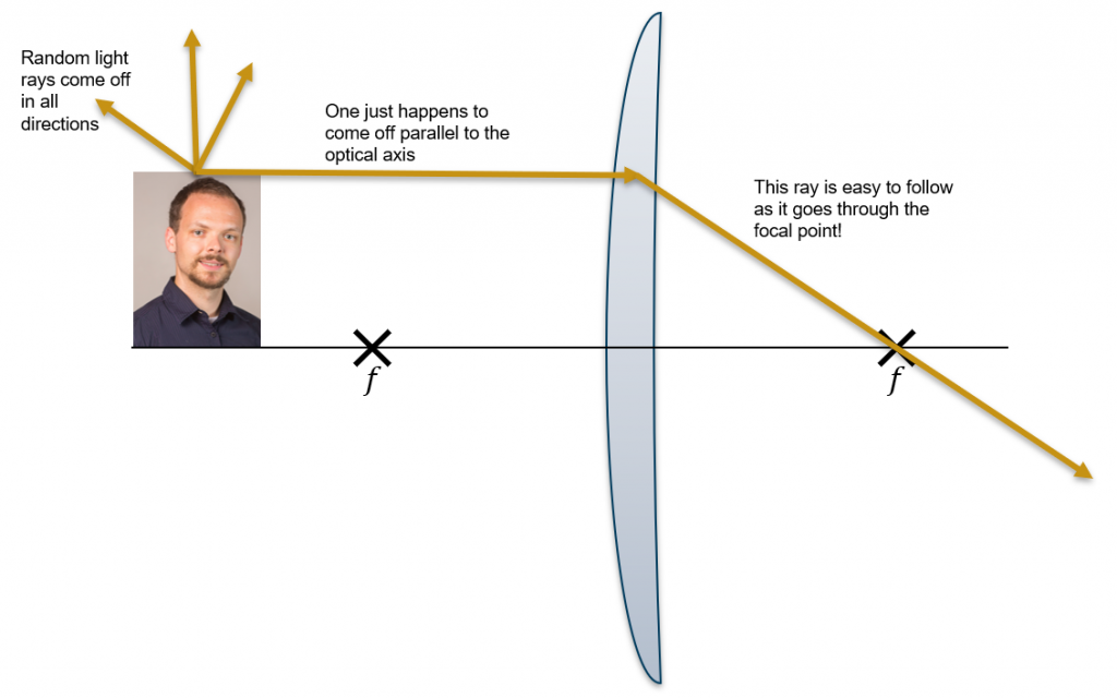
So what is ray tracing? If an object emits light, it emits light in all directions. If the object is visible by reflecting light from another source, your face is visible because it reflects light from the surroundings, that reflected light is diffuse and goes in all directions. Also keep in mind, that typical objects emit huge (1030) numbers of photons. Thus, there are effectively photons going in every conceivable direction as shown in Figure 1.
Figure 1: While rays come off in all directions, we follow the rays which are easy – like one that goes through the lens parallel to the optical axis and then through the focal point.
Ray tracing allows us to follow very specific photons: photons which will easy to follow because of the paths they take. For example, we know from the last chapter, that a photon that enters a converging lens parallel to the optical axis will go through the focal point as shown in Figure 2 below. Since there are so many photons, leaving your face, one will go parallel to the optical axis and then through the lens and towards the focal point as shown in Figure 1.
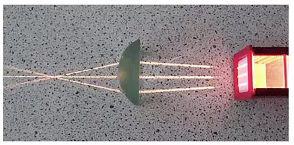
Figure 2: Incoming parallel rays converge to the focal point of a converging lens.
Throughout the next few sections, we will go through the particular rays to follow for the different :
For each optical element, there will be three rays to follow for any object a finite distance away (if the object is infinitely far away, then the rays come in parallel and we saw what happens with parallel rays in the previous chapter). The three rays to follow are:
Our three rays that we will follow
A ray that comes in parallel to the optical axis leaves using a focal point. If the optical element is (like a concave mirror or convex lens) then use a focal point that brings the ray towards the optical axis.
A ray that aims for the center of a lens or mirror will go straight.
The center of a lens is the middle: this ray will travel un-deflected as though the lens was not there.
The center of a mirror is the geometric center: this ray will hit the mirror at a 90o angle and bounce straight back.
A ray that comes in using a focal point will exit parallel to the optical axis.
Instructor’s Note
Your quiz will cover:
For a given ray, you need to be able to determine where it will go for each of these basic optical elements
We will NOT expect you to be able to interpret the results, do calculations, or consider multiple elements. We will do that in class.
Ray Tracing for Converging Lenses
Instructor’s Note
All of the following sections are presented both as video and with a text-based transcript. Normally, I feel that the two presentations are equivalent. In this particular case, however, I feel that most students will learn more by watching the videos particularly if you follow along on your own sheet of paper.
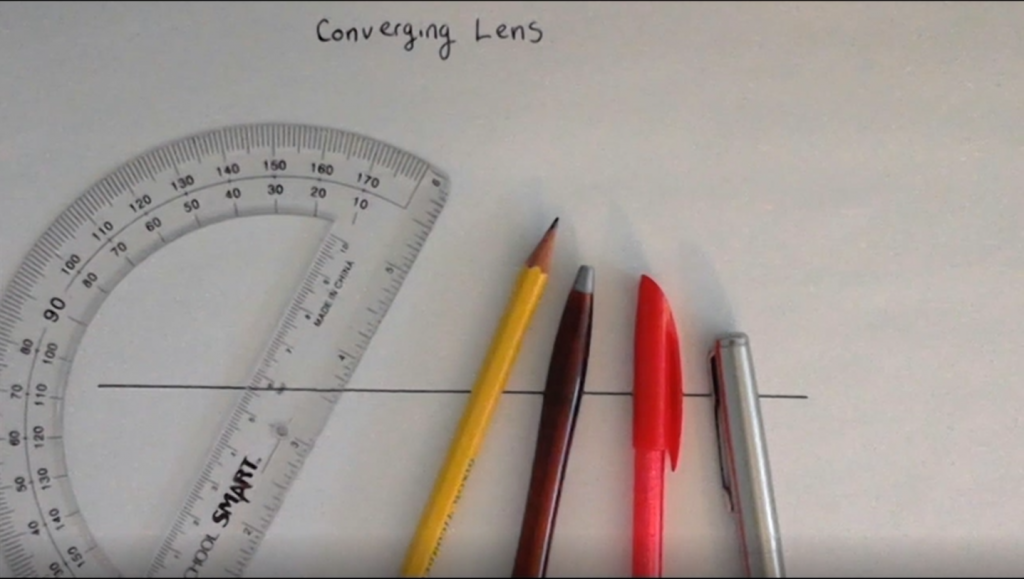
In this section, we are going to explore how to draw ray diagrams for the first of our four types of optical elements: the converging lens. Now, these videos use pictures of paper drawings to really show you the mechanics of how to draw these things out by hand. You will be expected to draw ray diagrams on an exam. To draw ray diagrams, it really helps to have a few things: one it helps to have pens in a couple of different colors: black, red, and blue. I also like to have a pencil which gives me four colors. You also
really need a protractor, which was labeled on the syllabus as one of the things you need for this course.
Get started drawing a ray diagram for converging lens, by drawing an optical axis. Now, put your lens on this axis somewhere, kind of in the middle to give yourself some room to work. Draw the center of the lens first, using your protractor to make sure it is perpendicular to your optical axis and that all your lines are straight. Trying to ray diagrams freehand will NOT work! You need your lines to be straight you need your angles to be precise there’s no way you’ll ever get these diagrams to work properly if you’re trying to draw them freehand.
Since I’m not an artist, and drawing the lens itself takes time, you’ll often see me identify a converging lens just with a symbol that looks like a line with arrows
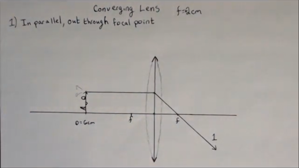
on both ends. These arrows are meant to indicate that the lens gets thicker towards the middle than it does towards the ends. You’ll see when we do the diverging lens, we’ll use a different symbol. Now put an object about six centimeters away from my lens. Your object might be a little face or something like that. Again I’m no artist, often you’ll see people put a little arrow just to help identify which way is up. We also need to know the focal lengths for our lens: let’s put our focal length for this example at two centimeters. It’s going to be a positive focal length because our lens is converging. Measure out your two focal points and label them with . Now, we have a set-up, and at this point we can go through and actually start drawing our rays.
Ray number one is in parallel out through focal point. Recall, light rays are going in all directions off the top of this object. One of these is a ray going off towards the lens parallel to the optical axis. When this ray hits the lens, it’s going to go out through the focal point because that’s what a focal point is for a converging lens: converging lenses convert incoming light that’s parallel and bend them to their focal points. You’ll notice we’re pretending that all the bending happens here at the center of the lens and that’s due to the thin lens approximation that was discussed in the previous chapter.
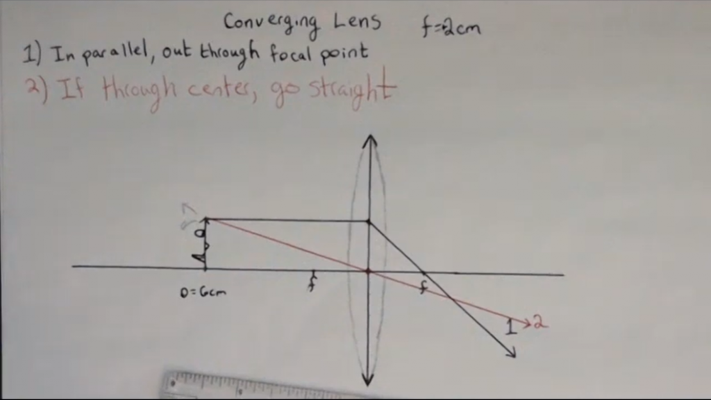
The second ray is the rule that if a ray through the center goes straight. In the case of a lens, the center is where the lens meets the optical axis: by definition the optical axis goes through the center of the lens (It may not look like it in my drawings because I’m not much of an artist!). So ray number two goes straight through the middle.
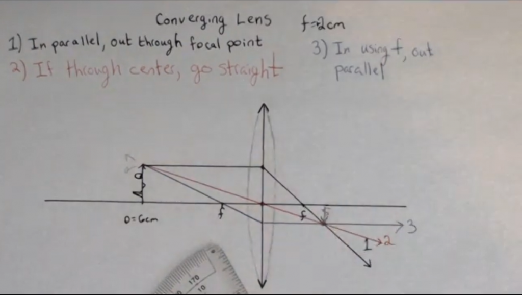
Ray number three, remember, is in using focal point out parallel. Now in this case, we’ve already used the focal point on the far side of the lens from the object. Therefore, this time we’re going to come in using the focal point we haven’t used yet, the one on the same side as the object. Out of all the infinite numbers of rays, we are going to follow the one which just happens to come in towards the lens going for this near focal point. This ray is going to go out parallel to our optical axis.
You can see that in this particular case, all of our ray’s happen to converge on the far side of the lens. As we’ll discuss in class, that is going to be the location of our image. We’ll talk more about that in class. What you need to know right now is how to draw these three rays:
In parallel, out using the focal point.
Straight through the center.
In through the focal point, and out parallel
Simulation
Below is a flash simulation (you may need to click and allow flash) that shows the paths of rays through a converging lens. A few things to explore:
Click “Principal Rays” to see the rays used in the ray diagrams discussed in the video.
Click “Many Rays” to see the fact that there are a bunch of rays coming from the object that all converge to the point, not just the ones we saw in the ray diagram. You will see that some even miss the lens entirely and just go straight!
Homework Problem
Problem 23: Drawing ray diagrams for converging lenses.
Ray tracing for Diverging Lenses
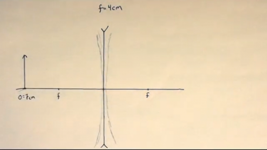
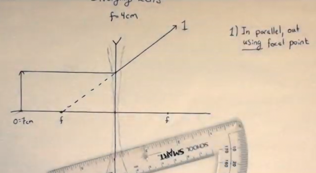
In this section, we will be drawing ray diagrams with diverging lenses. To get setup draw your optical axis and put your lens in the middle: make it pretty big. Always give yourself room to work when you’re drawing these things. This time we’re doing not a converging lens but a diverging lens. A diverging lens is, as you know, much thinner in the middle than it is on the outside. Because clearly my ability to draw diverging lens is even worse than my ability to draw converging lenses, I’ll often use arrow heads pointing towards the center of the lens to indicate that it’s thinner in the middle than it is on the outside. For this example, we’re going to use a focal length of 4 centimeters: one focal point on each side labelled . We will put our object 7 centimeters away. Give it a pretty good height: make it like three centimeters tall.
Now we once again go with our same process: ray number one is “in parallel out using a focal point.” You will notice notice I’m using the word using not the word through because the ray will not actually go through a focal point. The ray comes in parallel, use your protractor to make sure that the ray is parallel to the optical axis. Since this is a
diverging lens, it’s not going to bring the ray towards the optical axis; it’s going to cause the ray to diverge away from the optical axis as if the light had come from this focal point on the same side as the object. That is why I say not through but using. The light is going to diverge as if it came from this focal point on the left. I usually include a dashed line to help me get my line straight.’
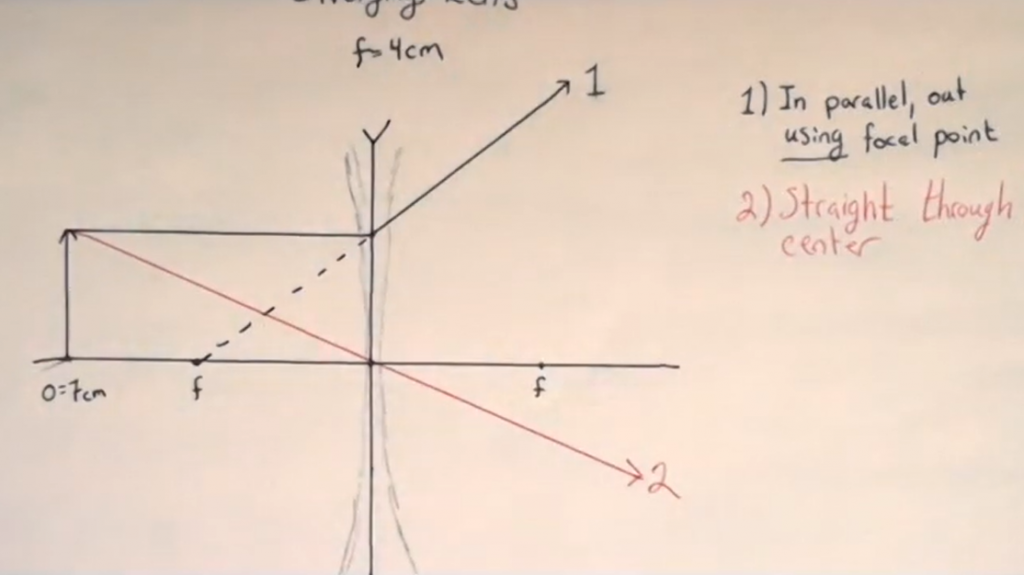
Ray number two, “straight through the middle,” which is pretty straightforward. The middle is where our optical axis meets our optical element.
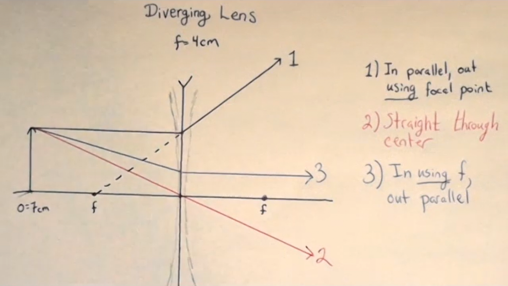
Then we’ve got ray number three, “in using a focal point, out parallel.” Again, you’ll notice I’m using the word using. In this particular case, I’ve already used the left focal point, and I can’t use it again. Therefore, I have to use the other one on the far side from the object. So I’m gonna come in as if I were going for that focal point, but then I hit the lens and, instead of continuing on, I go out parallel to the optical axis. That is ray number 3.
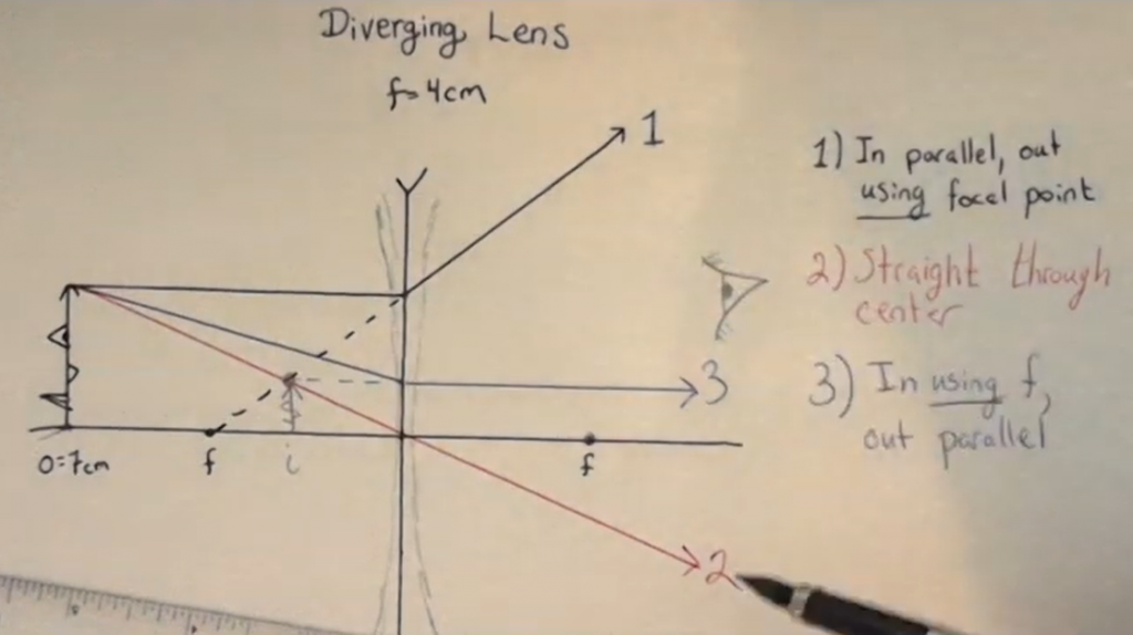
You’ll notice these rays are spraying out, which they should. This is a diverging lens after all, the rays should diverge, and they do. Thus, they don’t converge to a point anywhere like we did saw in the last example. However, what if your eye were over here on the right looking through the lens at the object, what would you see? Well your brain assumes that light travels in straight lines, because in most of your experience it does. So your brain is going to assume that all these light rays emanated from this point and traveled in a straight lines. Thus, we will have our image over here on the left, the same side as the object! We’ll discuss this part more in class, but I thought I would just expose you to it while we’re here. What you need to know right now is how to draw these three rays.
Homework Problem
Problem 24: Ray diagrams with diverging lenses.
Ray Tracing for Concave Mirrors
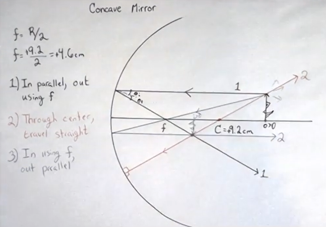
In this section, I am going to show you how to draw the ray diagram for a concave mirror now. In this particular class, we’re only interested in mirrors that are parts of circles or flat. In class, we will provide you a nice little drafting tool to help you draw mirrors that are circles but for the purposes of this video, I’m going to use a compass. We will begin by drawing a circular mirror using my compass. Note that for mirrors, the is the geometric center of the circle. For lenses, in contrast, the center is the middle part so it’s a slight difference in terminology. Now I will add my optical axis which connects the center of the mirror and goes away from it (you’re going to really need a protractor to do all of this stuff!). Next, I need to measure how big my circle actually is. I can see from measuring it that my center is 9.2 cm away from the vertex, which by the sign conventions discussed in the last chapter, since this is a concave mirror, we’re going to think of our radius as being positive.
Now, a fundamental property of all spherical mirrors is that the focal length is half of the radius . That is generally true for all spherical mirrors. Therefore, in this case, the focal length is going to be 4.6cm. I can, therefore, measure 4.6 cm away from the vertex and mark a little point which will my focal point. Now, all we need is an object. In this example, we’re going to place our object nice and and far outside our center. It will be outside the center of curvature. Let’s make an object that’s gonna have some some height to it. I’m actually gonna make it as tall as my protractor ruler for a reason that’ll become hopefully apparent in a moment. As usual, we like to put a little arrow on our object so we know which way is up but you can think of it as being a face, or a tree, or a candle, or whatever you want. Arrows are just easy to draw. Recall, there are photons coming off of this object in all directions and we’re just going to choose the three photons that are easiest for us to follow.
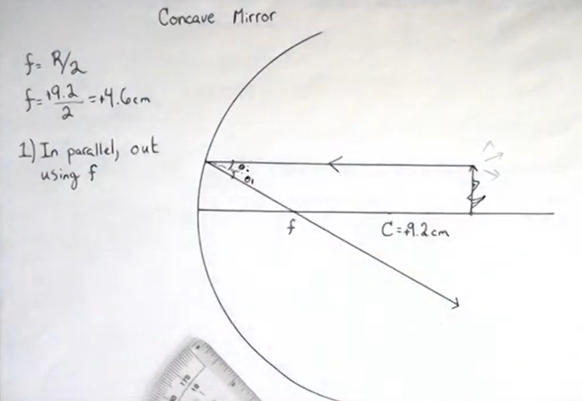
The nice thing about phrasing the ray diagram rules the way I have at the beginning of this chapter is the same three rays that we’ve been doing for lenses still work: we just have to think about them a little bit differently. The first ray, just as for lenses, is “in parallel, out using the focal point.” We are therefore, going to draw our first ray coming in parallel (now you can see why I’ve made my object the exact same thickness as my protractor – it makes drawing a parallel ray pretty easy) and it’s going to then go out through my focal point. You can see why by zooming in over here, our law of reflection: the incoming angle and the outgoing angle are the same.
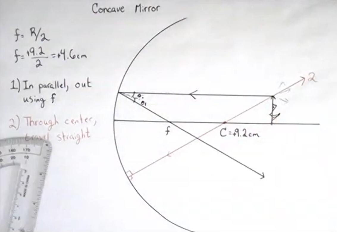
Ray number two: “rays that go through the center travel straight.” Notice again that the phrasing of how we describe our rays is exactly the same for mirrors and lenses. In this case, however, the center is the center of the circle, not physically on the mirror. That point, where the mirror meets the optical axis, is called the vertex. A ray that goes through the center will travel in a straight line: that ray will come in hit the mirror and end up bouncing to travel straight back the way it came. You can see that such a ray meets the mirror at 90 degrees so it bounces straight in-and-out.
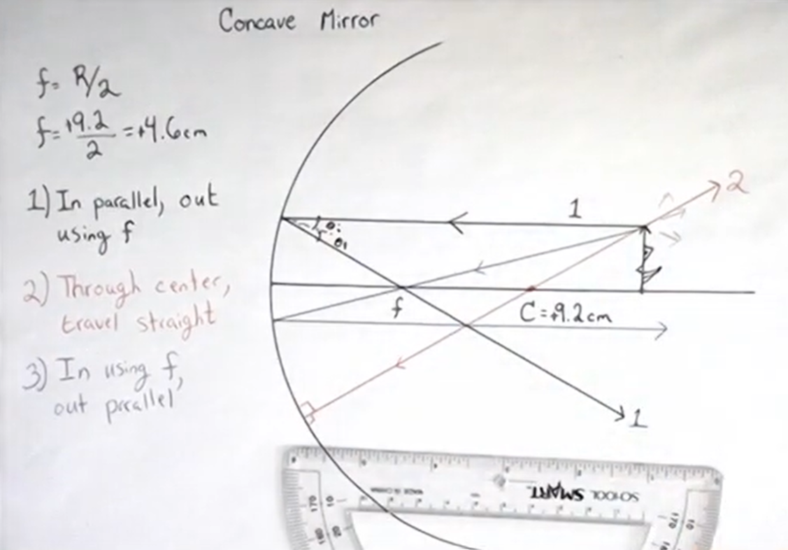
Finally, ray number three again follow the same rules as the lens: “in using the focal point out parallel.” Now, lenses have two focal points, one on each side, but mirrors only only have the one. Thus, we don’t have to worry about which focal point to use: mirror only has one, so that makes it maybe a little bit easier. Our ray is going to come in using our focal point and then going to go out parallel to our optical axis.
You will see that all of these rays actually converge at this point right in front of the mirror. That point is where our image is going to be. Thus, we are
going to have an image distance that’s positive as it is on the side of the outgoing light. The thing with mirrors is that the incoming side and the outgoing side are the same side of the mirror. We are therefore going to have a positive image distance and a positive object distance. Moreover, our image is going to be in the previous chapter when we discussed looking in the inside of a spoon at some length. We mentioned that the image appears to hover in front of the spoon a little bit: here we see exactly where that image is. We will talk more in class about why this is the image, how to characterize that image, and some other aspects of interpreting this diagram. What I really need you to know for right now is how to draw these three rays.
Homework Problem
Problem 25: Ray diagrams with concave mirrors.
Ray Tracing for Convex Mirrors
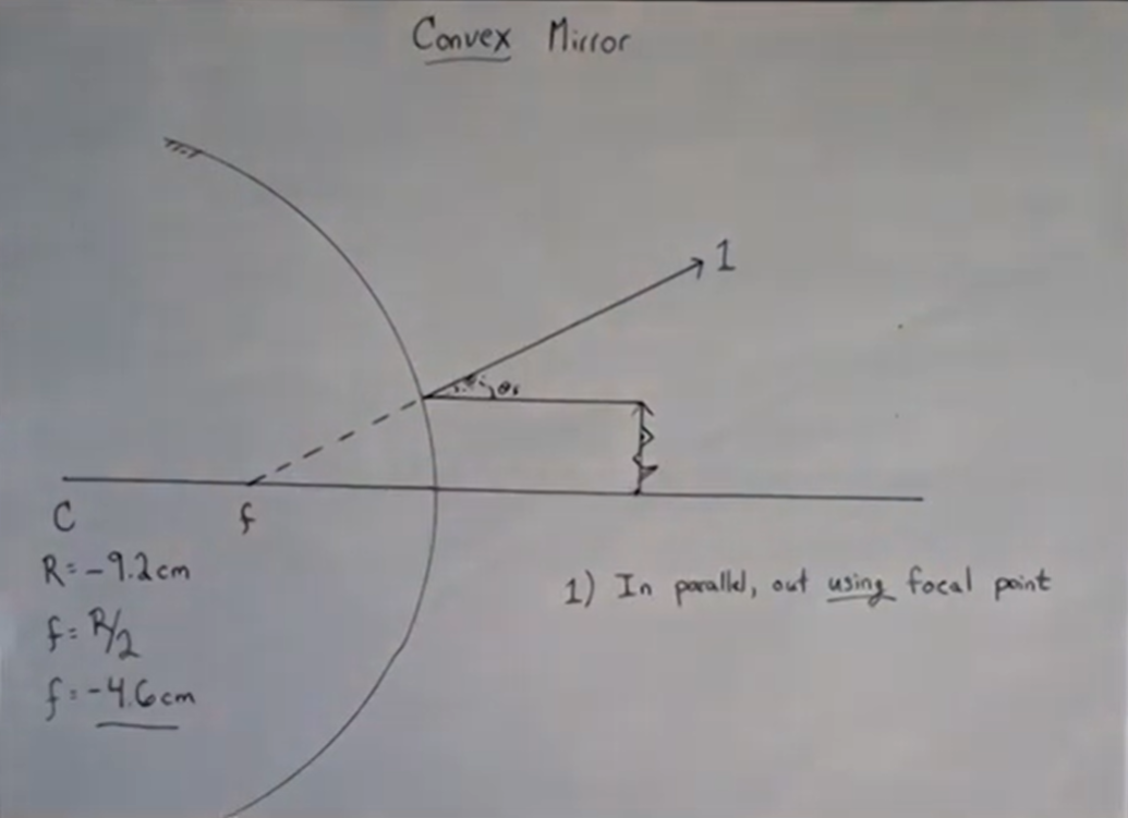
Now for the last optical element, where we draw the ray diagram for a convex mirror. Once again I’m going to use my compass to draw the spherical mirror to begin. In class, I’ll give you a tool to help with this but here I’m going to use a compass to help me draw a nice circle. Again, I use the center of the circle to define my optical axis. My circle has a radius of 9.2cm, but since it’s a convex mirror our sign conventions say that the radius should be negative: . Just as with a
concave mirror, the focal length is half the radius . Therefore, the focal length is going to be negative: measured from the vertex. Now go and put an object on the other side from the center, because, remember we’re looking at a convex mirror – we’re looking at the back of a spoon. In this example, let’s put it 5 cm outside. Just as in the last section, I am going to make my object the thickness of my protractor ruler. That will make drawing a nice incoming
parallel right easy. As always, we draw it as an arrow just so it’s easy to tell which way is up but you can think of it as a little face, a tree, a candle, it could be anything.
Once again, our rules are the same: the first ray is, as always, “in parallel out using the focal point.” Thus, I draw my incoming ray parallel. now I can’t go through because it’s a mirror, the ray has to bounce instead. You will also notice that again I use the verb using instead of through to help me remember that I can’t go throughthe focal point that’s behind the mirror. Thus, the ray is going to go out using the focal point: this ray is gonna bounce as if it had come from the focal point. That is what the focal point for a convex mirror means. Thus, we have ray number one and, as always, we can see that .
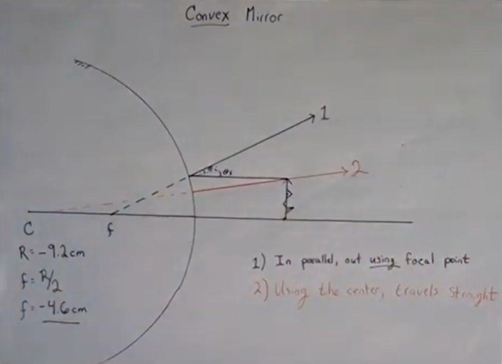
Ray number two: “a ray using the center travels straight.” For this ray, we are going to aim for the center of the mirror’s circle, but it can’t go through (because that’s a mirror) so instead it will bounce and head back off directly the way it came.
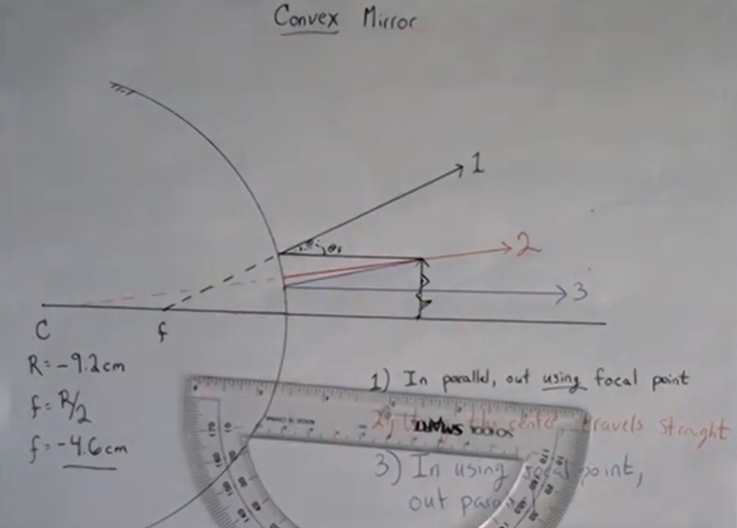
Ray number three: “in using the focal point out parallel.” This time we’re going to consider a ray that comes in as if it were going for the focal point behind the mirror and is going to go out parallel to the optical axis.
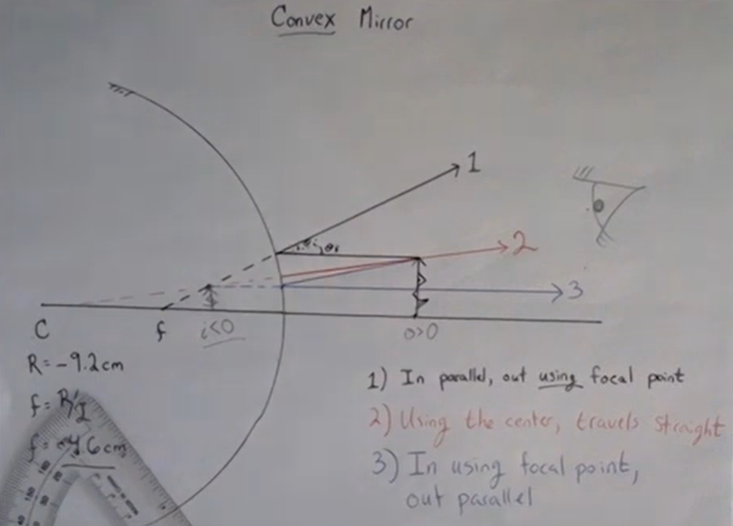
Now, as with the diverging lens describe above, these three rays don’t converge anywhere; they’re spraying out as they leave the mirror. This is a diverging optical element so they should spread out. However as with the diverging lens, if your eye is behind the object looking at this whole thing what your eye going to see is these three photons and it’s going to assume these photons traveled in straight lines. All the photons appear to have originated from a point behind the mirror. That point is where our image is going to be. In this particular case, we have an object distance to the right that is positive, because the object is on the same side is the incoming light but we have a negative image distance because the light while it comes in on the right, also goes out on the right because of the mirror. The image is on the reverse side from this outgoing light, so the image distance is negative. Ultimately, we see a little upright erect image behind the mirror. If you look in the back of a spoon, as was shown in the last chapter, that’s what you see you see: a littlemini version of yourself erect behind the spoon.
Homework Problem
Problem 26: Ray diagrams with convex mirrors.
When the image is the same orientation as the object
When the image is upside-down with respect to the object.
ratio of image height to object height
any lens or mirror
A mirror that bends away from the light source (
A mirror that bends towards the incoming light )
a convex lens in which light rays that enter it parallel to its axis converge at a single point on the opposite side
a concave lens in which light rays that enter it parallel to its axis bend away (diverge) from its axis
Bring light rays to a point.
For a lens, where the lens is thickest.
For a mirror, the center is the center of curvature.


 . Now, we have a set-up, and at this point we can go through and actually start drawing our rays.
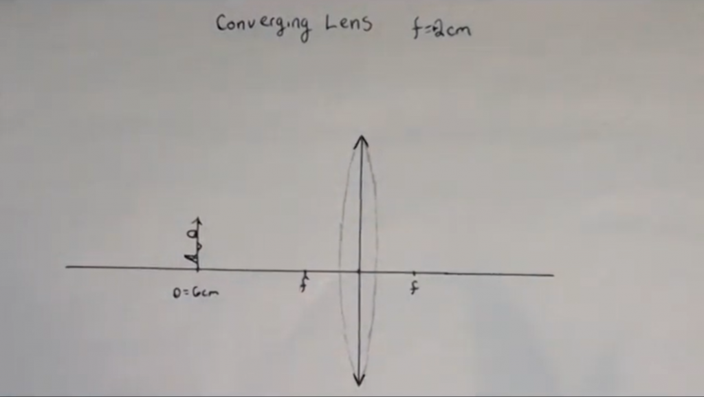
 . That is generally true for all spherical mirrors. Therefore, in this case, the focal length is going to be 4.6cm. I can, therefore, measure 4.6 cm away from the vertex and mark a little point which will my focal point. Now, all we need is an object. In this example, we’re going to place our object nice and and far outside our center. It will be outside the center of curvature. Let’s make an object that’s gonna have some some height to it. I’m actually gonna make it as tall as my protractor ruler for a reason that’ll become hopefully apparent in a moment. As usual, we like to put a little arrow on our object so we know which way is up but you can think of it as being a face, or a tree, or a candle, or whatever you want. Arrows are just easy to draw. Recall, there are photons coming off of this object in all directions and we’re just going to choose the three photons that are easiest for us to follow.
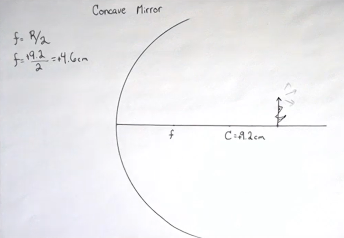
 . Just as with a
 measured from the vertex. Now go and put an object on the other side from the center, because, remember we’re looking at a convex mirror – we’re looking at the back of a spoon. In this example, let’s put it 5 cm outside. Just as in the last section, I am going to make my object the thickness of my protractor ruler. That will make drawing a nice incoming
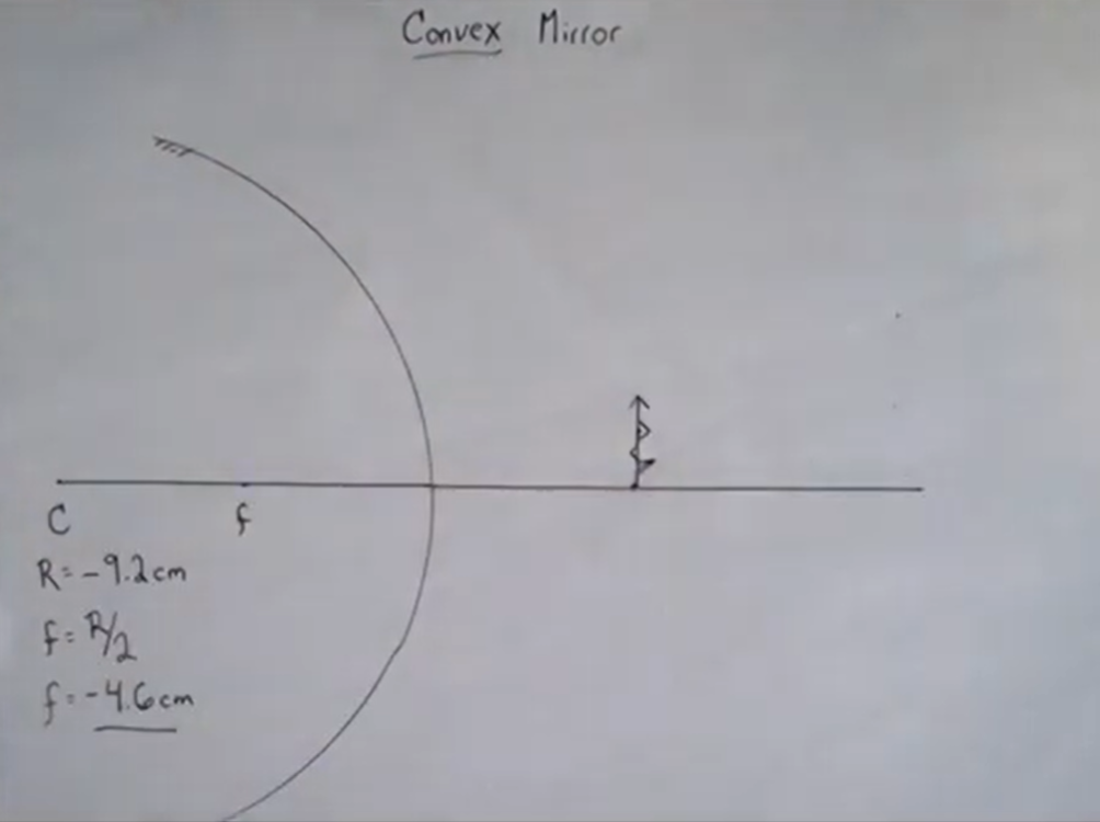
 .
.