
32 Magnet Fields and What They Do
Magnetic Fields and Magnetic Field Lines
Derived from Magnetic Fields and Lines by
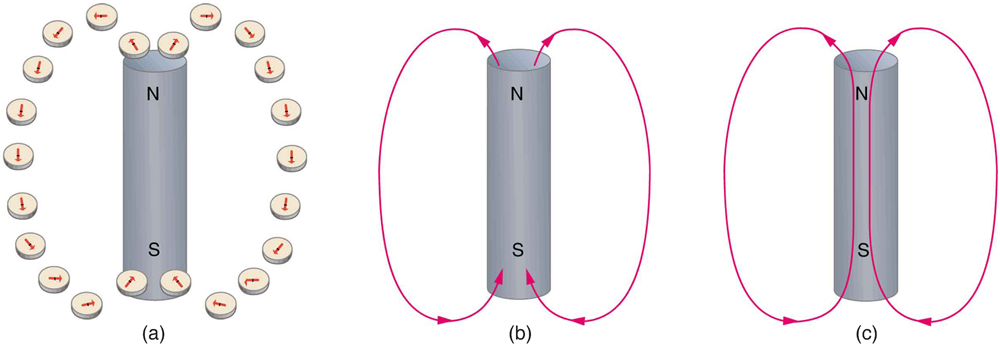
Einstein is said to have been fascinated by a compass as a child, perhaps musing on how the needle felt a force without direct physical contact. His ability to think deeply and clearly about action at a distance, particularly for gravitational, electric, and magnetic forces, later enabled him to create his revolutionary theory of relativity. Since magnetic forces act at a distance, we define a magnetic field to represent magnetic forces. The pictorial representation of magnetic field lines is very useful in visualizing the strength and direction of the magnetic field. As shown in Figure 1, the direction of magnetic field lines is defined to be the direction in which the north end of a compass needle points. The magnetic field is traditionally called the B-field.

Instructor’s Note
Why do we use B for magnetic field? I have no idea.
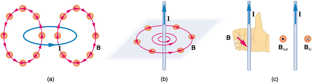
Small compasses used to test a magnetic field will not disturb it. (This is analogous to the way we tested electric fields with a small test charge. In both cases, the fields represent only the object creating them and not the probe testing them.) Figure 2 shows how the magnetic field appears for a current loop and a long straight wire, as could be explored with small compasses. A small compass placed in these fields will align itself parallel to the field line at its location, with its north pole pointing in the direction of B. Note the symbols used for field into and out of the paper.
Making Connections: Concept of a Field
A field is a way of mapping forces surrounding any object that can act on another object at a distance without an apparent physical connection. The field represents the object generating it. Gravitational fields map gravitational forces, electric fields map electrical forces, and magnetic fields map magnetic forces.
Extensive exploration of magnetic fields has revealed a number of hard-and-fast rules. We use magnetic field lines to represent the field. The properties of magnetic field lines can be summarized by these rules:
- The direction of the magnetic field is tangent to the field line at any point in space. A small compass will point in the direction of the field line.
- The strength of the field is proportional to the closeness of the lines. It is exactly proportional to the number of lines per unit area perpendicular to the lines (called the areal density).
- Magnetic field lines can never cross, meaning that the field is unique at any point in space.
- Magnetic field lines are continuous, forming closed loops without beginning or end. They go from the north pole to the south pole.
The last property is related to the fact that the north and south poles cannot be separated. It is a distinct difference from electric field lines, which begin and end on the positive and negative charges. If magnetic monopoles existed, then magnetic field lines would begin and end on them.
Section Summary
- Magnetic fields can be pictorially represented by magnetic field lines, the properties of which are as follows:
- The field is tangent to the magnetic field line.
- Field strength is proportional to the line density.
- Field lines cannot cross.
- Field lines are continuous loops.
Magnetic Field Strength: Force on a Moving Charge in a Magnetic Field
Derived from Magnetic Field Strength: Force on a Moving Charge in a Magnetic Field by
Instructor’s Note
- Only moving charges (i.e., currents) experience forces due to magnetic fields
- The letters in the expression
 . As far as prep is concerned, the angle theta will always be 90 degrees, so sine will always be 1.
What is the mechanism by which one magnet exerts a force on another? The answer is related to the fact that all magnetism is caused by current, the flow of charge. Magnetic fields exert forces on moving charges, and so they exert forces on other magnets, all of which have moving charges.
Right Hand Rule 1
The magnetic force on a moving charge is one of the most fundamental known. Magnetic force is as important as the electrostatic or Coulomb force. Yet the magnetic force is more complex, in both the number of factors that affect it and in its direction, than the relatively simple Coulomb force. The magnitude of the magnetic force  on a charge
  moving at a speed
  in a magnetic field of strength
  is given by

Instructor’s Note
The only thing about the angle you need to know is that if the velocity is PARALLEL to the field, then there is no force!
where  is the angle between the directions of and . This force is often called the Lorentz force. In fact, this is how we define the magnetic field strength —in terms of the force on a charged particle moving in a magnetic field. The SI unit for magnetic field strength is called the tesla (T) after the eccentric but brilliant inventor Nikola Tesla (1856–1943). To determine how the tesla relates to other SI units, we solve for .

Instructor’s Note
We will spend time in class thinking about these complex directions!
Because  is unitless, the tesla is

(note that C/s = A).
Another smaller unit, called the gauss (G), where  , is sometimes used. The strongest permanent magnets have fields near 2 T; superconducting electromagnets may attain 10 T or more. The Earth’s magnetic field on its surface is only about
  , or 0.5 G.
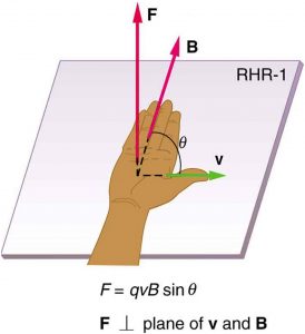
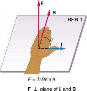
The direction of the magnetic force is perpendicular to the plane formed by and , as determined by the right hand rule 1 (or RHR-1), which is illustrated in Figure 3. RHR-1 states that, to determine the direction of the magnetic force on a positive moving charge, you point the thumb of the right hand in the direction of , the fingers in the direction of , and a perpendicular to the palm points in the direction of . One way to remember this is that there is one velocity, and so the thumb represents it. There are many field lines, and so the fingers represent them. The force is in the direction you would push with your palm. The force on a negative charge is in exactly the opposite direction to that on a positive charge.
Instructor’s Note
Again, we will spend more time in class going over these complex directions!
Magnetism is WAY more interesting then just bar magnets!
 and and follows right-hand rule–1 (RHR-1) as shown. The magnitude of the force is proportional to
  , and the sine of the angle between and .
Making Connections: Charges and Magnets
There is no magnetic force on static charges. However, there is a magnetic force on moving charges. When charges are stationary, their electric fields do not affect magnets. But when charges move, they produce magnetic fields that exert forces on other magnets. When there is relative motion, a connection between electric and magnetic fields emerges—each affects the other.
Calculating Magnetic forces
Instructor’s Note
This is a good example, as I will expect you to solve for the numbers in problems such as this on your homework and on your quiz. I will NOT ask you about the directions.
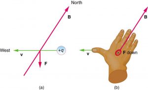
With the exception of compasses, you seldom see or personally experience forces due to the Earth’s small magnetic field. To illustrate this, suppose that in a physics lab you rub a glass rod with silk, placing a 20-nC positive charge on it. Calculate the force on the rod due to the Earth’s magnetic field  , if you throw it with a horizontal velocity of 10 m/s due west in a place where the Earth’s field is due north parallel to the ground. (The direction of the force is determined with right hand rule 1 as shown in Figure 4.)
Strategy
We are given the charge, its velocity, and the magnetic field strength and direction. We can thus use the equation to find the force.
Solution
The magnetic force is
We see that  , since the angle between the velocity and the direction of the field is 90º. Entering the other given quantities yields

 .
.
Discussion
This force is completely negligible on any macroscopic object, consistent with experience. (It is calculated to only one digit, since the Earth’s field varies with location and is given to only one digit.) The Earth’s magnetic field, however, does produce very important effects, particularly on submicroscopic particles. Some of these are explored in Force on a Moving Charge in a Magnetic Field: Examples and Applications.
Section Summary
- Magnetic fields exert a force on a moving charge q, the magnitude of which is
where is the angle between the directions of and .
- The SI unit for magnetic field strength is the tesla (T), which is related to other units by

- The direction of the force on a moving charge is given by right hand rule 1 (RHR-1): Point the thumb of the right hand in the direction of , the fingers in the direction of , and a perpendicular to the palm points in the direction of .
- The force is perpendicular to the plane formed by
 and
and  . Since the force is zero if is parallel to , charged particles often follow magnetic field lines rather than cross them.
3. Units of magnetic field.
4. What will feel a magnetic force.
5. What will feel a magnetic force – macroscopic objects.
6. Thinking about the magnetic forces on charged particles.
7. Magnetic force on an airplane.
8. Magnetic force on a baseball.
9. Magnetic force on an electron at an angle to  .
.
Magnetic Force on a Current-Carrying Conductor
Derived from Magnetic Force on a Current-Carrying Conductor by
Instructor’s Note
- Know that only currents perpendicular to magnetic fields experience magnetic forces
- Be able to calculate the magnetic force on a section of wire of length L carrying a current I perpendicular to a magnetic field B using F = ILB
We will, as with charged particles, deal with the directions and the case of currents neither parallel nor perpendicular to magnetic fields in class.
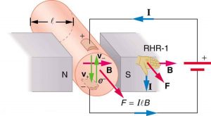
Because charges ordinarily cannot escape a conductor, the magnetic force on charges moving in a conductor is transmitted to the conductor itself.
We can derive an expression for the magnetic force on a current by taking a sum of the magnetic forces on individual charges. (The forces add because they are in the same direction.) The force on an individual charge moving at the drift velocity  is given by
  . Taking to be uniform over a length of wire
  and zero elsewhere, the total magnetic force on the wire is then
  , where
  is the number of charge carriers in the section of wire of length . Now,
  , where
  is the number of charge carriers per unit volume and
  is the volume of wire in the field. Noting that
  , where
  is the cross-sectional area of the wire, then the force on the wire is
  . Gathering terms,

Because  (see Current),

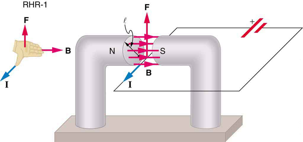
is the equation for magnetic force on a length of wire carrying a current  in a uniform magnetic field , as shown in Figure 6. If we divide both sides of this expression by , we find that the magnetic force per unit length of wire in a uniform field is
  . The direction of this force is given by RHR-1, with the thumb in the direction of the current . Then, with the fingers in the direction of , a perpendicular to the palm points in the direction of , as in Figure 6.
 . Its direction is given by RHR-1.
Calculating Magnetic Force on a Current-Carrying Wire: A Strong Magnetic Field
Calculate the force on the wire shown in Figure 7, given  and
and  .
.
Strategy
The force can be found with the given information by using and noting that the angle between and is 90º, so that .
Solution
Entering the given values into yields
 .
.
The units for tesla are  ; thus,
 .
.
Discussion
This large magnetic field creates a significant force on a small length of wire.
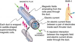
Magnetic force on current-carrying conductors is used to convert electric energy to work. (Motors are a prime example—they employ loops of wire and are considered in the next section.) Magnetohydrodynamics (MHD) is the technical name given to a clever application where magnetic force pumps fluids without moving mechanical parts. (See Figure 7.)
A strong magnetic field is applied across a tube, and a current is passed through the fluid at right angles to the field, resulting in a force on the fluid parallel to the tube axis, as shown. The absence of moving parts makes this attractive for moving a hot, chemically active substance, such as the liquid sodium employed in some nuclear reactors. Experimental artificial hearts are being tested with this technique for pumping blood, perhaps circumventing the adverse effects of mechanical pumps. (Cell membranes, however, are affected by the large fields needed in MHD, delaying its practical application in humans.) MHD propulsion for nuclear submarines has been proposed because it could be considerably quieter than conventional propeller drives. The deterrent value of nuclear submarines is based on their ability to hide and survive a first or second nuclear strike. As we slowly disassemble our nuclear weapons arsenals, the submarine branch will be the last to be decommissioned because of this ability (See Figure 8.) Existing MHD drives are heavy and inefficient—much development work is needed.
Section Summary
- The magnetic force on current-carrying conductors is given by
,
where is the current, is the length of a straight conductor in a uniform magnetic field , and is the angle between and . The force follows RHR-1 with the thumb in the direction of .
10. When is the force on a current carrying wire the strongest?
11. Determine the field from the force on a wire.
12. Determine the angle between a wire and the field.
