
28 Circuits
Electric Power and Energy
Derived from Electric Power and Energy by OpenStax. You may find it useful to review the section on Power from Some Energy-Related Ideas that Might be New or are Particularly Important.
Power in Electric Circuits
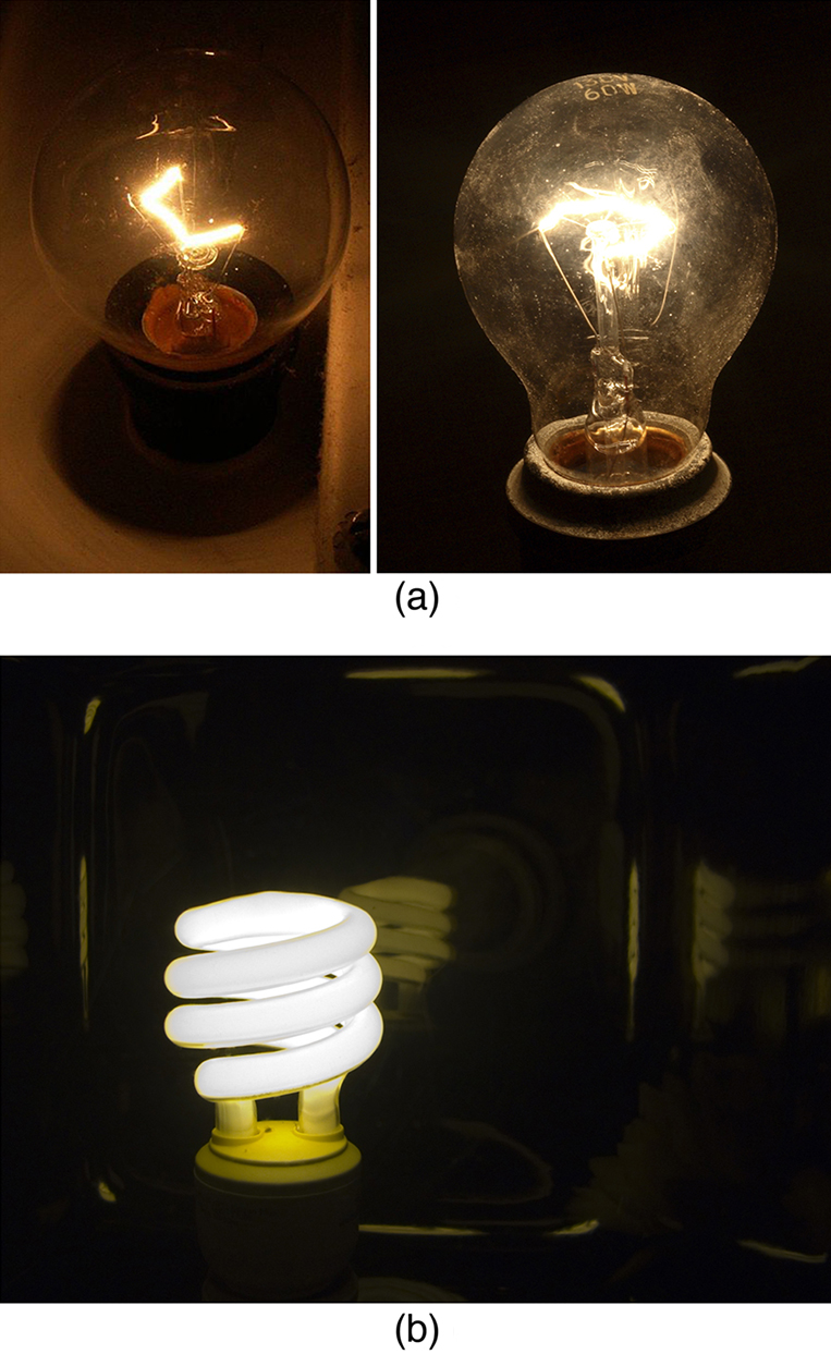
Power is associated by many people with electricity. Knowing that power is the rate of energy use or energy conversion, what is the expression for electric power? Power transmission lines might come to mind. We also think of light bulbs in terms of their power ratings in watts. Let us compare a 25-W bulb with a 60-W bulb. (See Figure 1(a).) Since both operate on the same voltage, the 60-W bulb must draw more current to have a greater power rating. Thus, the 60-W bulb’s resistance must be lower than that of a 25-W bulb (think about Ohm’s Law!). If we increase voltage, we also increase power. For example, when a 25-W bulb that is designed to operate on 120 V is connected to 240 V, it briefly glows very brightly and then burns out. Precisely how are voltage, current, and resistance related to electric power?
Electric energy depends on both the voltage involved and the charge moved. This is expressed most simply as  , where
  is the charge moved and
  is the voltage (or more precisely, the potential difference the charge moves through). Power is the rate at which energy is moved, and so electric power is
 .
.
Recognizing that current is  (note that
  here), the expression for power becomes
 .
.
Electric power ( ) is simply the product of current times voltage. Power has familiar units of watts. Thus,
  . For example, cars often have one or more auxiliary power outlets with which you can charge a cell phone or other electronic devices. These outlets may be rated at 20 A, so that the circuit can deliver a maximum power
  . In some applications, electric power may be expressed as volt-amperes or even kilovolt-amperes (
 ).
).
To see the relationship of power to resistance, we combine Ohm’s law with . Substituting  gives
gives  . Similarly, substituting
  gives
gives  . Three expressions for electric power are listed together here for convenience:

 .
.
Note that the first equation is always valid, whereas the other two can be used only for resistors. In a simple circuit, with one voltage source and a single resistor, the power supplied by the voltage source and that dissipated by the resistor are identical. (In more complicated circuits, can be the power dissipated by a single device and not the total power in the circuit.)
Different insights can be gained from the three different expressions for electric power. For example,  implies that the lower the resistance connected to a given voltage source, the greater the power delivered. Furthermore, since voltage is squared in , the effect of applying a higher voltage is perhaps greater than expected. Thus, when the voltage is doubled to a 25-W bulb, its power nearly quadruples to about 100 W, burning it out. If the bulb’s resistance remained constant, its power would be exactly 100 W, but at the higher temperature, its resistance is higher, too.
Calculating Power Dissipation and Current: Hot and Cold Power
(a) Consider the examples given in the last chapter on Ohm’s Law. Then find the power dissipated by the car headlight in this example.
Strategy for (a)
For the hot headlight, we know voltage and current, so we can use to find the power.
Solution for (a)
Entering the known values of current and voltage for the hot headlight, we obtain
 .
.
Discussion for (a)
The 30 W dissipated by the hot headlight is typical.
The Cost of Electricity
The more electric appliances you use and the longer they are left on, the higher your electric bill. This familiar fact is based on the relationship between energy and power. You pay for the energy used. Because  , we see that

is the energy used by a device using power for a time interval  . For example, the more lightbulbs burning, the greater used; the longer they are on, the greater is. The energy unit on electric bills is the kilowatt-hour (
 ), consistent with the relationship . It is easy to estimate the cost of operating electric appliances if you have some idea of their power consumption rate in watts or kilowatts, the time they are on in hours, and the cost per kilowatt-hour for your electric utility. Kilowatt-hours, like all other specialized energy units such as food calories, can be converted to joules. You can prove to yourself that
  .
.
The electrical energy ( ) used can be reduced either by reducing the time of use or by reducing the power consumption of that appliance or fixture. This will not only reduce the cost, but it will also result in a reduced impact on the environment. Improvements to lighting are some of the fastest ways to reduce the electrical energy used in a home or business. About 20% of a home’s use of energy goes to lighting, while the number for commercial establishments is closer to 40%. Fluorescent lights are about 4 times more efficient than incandescent lights—this is true for both the long tubes and the compact fluorescent lights (CFL). (See Figure 1(b).) Thus, a 60-W incandescent bulb can be replaced by a 15-W CFL, which has the same brightness and color. CFLs have a bent tube inside a globe or a spiral-shaped tube, all connected to a standard screw-in base that fits standard incandescent light sockets. (Original problems with color, flicker, shape, and high initial investment for CFLs have been addressed in recent years.) The heat transfer from these CFLs is less, and they last up to 10 times longer. The significance of an investment in such bulbs is addressed in the next example. New white LED lights (which are clusters of small LED bulbs) are even more efficient (twice that of CFLs) and last 5 times longer than CFLs.
Making Connections: Energy, Power, and Time
The relationship is one that you will find useful in many different contexts. The energy your body uses in exercise is related to the power level and duration of your activity, for example. The amount of heating by a power source is related to the power level and the time it is applied. Even the radiation dose of an X-ray image is related to the power and time of exposure.
Calculating the Cost Effectiveness of Compact Fluorescent Lights (CFL)
If the cost of electricity in your area is 12 cents per kWh, what is the total cost (capital plus operation) of using a 60-W incandescent bulb for 1000 hours (the lifetime of that bulb) if the bulb costs 25 cents? (b) If we replace this bulb with a compact fluorescent light that provides the same light output, but at one-quarter the wattage, and which costs $1.50 but lasts 10 times longer (10,000 hours), what will that total cost be?
Strategy
To find the operating cost, we first find the energy used in kilowatt-hours and then multiply by the cost per kilowatt-hour.
Solution for (a)
The energy used in kilowatt-hours is found by entering the power and time into the expression for energy:
 .
.
In kilowatt-hours, this is
 .
.
Now the electricity cost is
 .
.
The total cost will be $7.20 for 1000 hours (about one-half year at 5 hours per day)
Solution for (b)
Since the CFL uses only 15 W and not 60 W, the electricity cost will be $7.20/4 = $1.80. The CFL will last 10 times longer than the incandescent, so the investment cost will be 1/10 of the bulb cost for that time period of use, or 0.1($1.50) = $0.15. Therefore, the total cost will be $1.95 for 1000 hours.
Discussion
Therefore, it is much cheaper to use the CFLs, even though the initial investment is higher. The increased cost of labor that a business must include for replacing the incandescent bulbs more often has not been figured in here.
Making Connections: Take-Home Experiment
1) Make a list of the power ratings on a range of appliances in your home or room. Explain why something like a toaster has a higher rating than a digital clock. Estimate the energy consumed by these appliances in an average day (by estimating their time of use). Some appliances might only state the operating current. If the household voltage is 120 V, then use .
2) Check out the total wattage used in the restrooms of your school’s floor or building. (You might need to assume the long fluorescent lights in use are rated at 32 W.) Suppose that the building was closed all weekend and that these lights were left on from 6 p.m. Friday until 8 a.m. Monday. What would this oversight cost? How about for an entire year of weekends?
Section Summary
- Electric power is the rate (in watts) at which energy is supplied by a source or dissipated by a device.
- Three expressions for electrical power are
,
,
and
 .
.
- The energy used by a device with a power over time is .
Kirchhoff’s Principles
This section is adapted from The University of Maryland BERG group.
The basic ideas that we have developed about how electric charges move in matter serve as a basis for analyzing a wide variety of electric circuits and devices and for modeling the electrical behavior of biological systems. But these circuits, devices, and models can quickly become quite complex. It becomes useful to establish a set of foothold ideas — principles that we can hold on to and refer back to in order to organize our thinking in complex situations — to provide a “stake in the ground” that we can trust and use to support our safety net of coherent and linked ideas.
The foothold principles for understanding electric currents were developed by the 19th-century German physicist, Gustav Kirchhoff (yes, two “h”s), are called Kirchhoff’s laws (or principles). (He also formulated laws of spectroscopy and thermochemistry.)
The (idealized) context for Kirchhoff’s principles
Kirchhoff’s principles are restrictions of more general electromagnetic laws (Maxwell’s equations, conservation of charge) to standard situations in electrical circuits. We’ll talk about them and use them in the context of analyzing connected networks of electrical devices — batteries, resistors, capacitors, and wires. Here’s how we will represent and idealize them:
| Batteries — devices that maintain a constant electrical pressure difference (voltage) across their terminals (like a water pump that raises water to a certain height). We use the symbol drawn at the right, with the longer line corresponding to the end of the battery with the higher potential. | ||
| Resistors — devices that have significant drag and oppose current. Pressure will drop across them when current is flowing through them. The resistor shown in the figure is of the kind used in hand-built electrical circuits. The stripes color-code the size of the resistor and its precision. We indicate them with the zig-zag symbol shown on the right. | 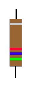 |
|
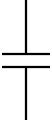
| Capacitors — devices that can maintain a charge separation in response to a pressure differential (voltage) applied across their plates. The symbol for a capacitor is the pair of parallel lines shown on the right. Be sure to distinguish between the symbol for a capacitor (parallel lines of equal length) and a battery (parallel lines of different length)! | 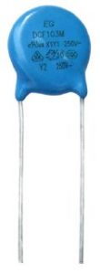 |
 |
| Wires — conductors that connect the other devices. We treat them as perfect conductors — having zero resistance. This approximation only works when there are other resistors in the circuit having significant resistance, compared to which the resistance of the wires is negligible. The symbol for a wire is just a line. and it could be straight or curved — makes no difference. |  |
Kirchhoff’s 1st (Flow) Principle
The first principle is basically a combination of two ideas:
- conservation of charge (the total amount of positive charge minus the total amount of negative charge is a constant).
- in electrical circuits, due to the strong repulsive forces between like charges, electrical elements remain neutral — there is no build-up of charge anywhere.
The principle is often called “the flow rule” and is stated as follows:
The total amount of current flowing into any volume in an electrical network equals the amount flowing out.
From our analysis of how a capacitor and a resistor both work, we know that this idea doesn’t hold when things are just getting started.
For example, when we charge a capacitor, charge is flowing into one side of the capacitor and out of the other: charge (of opposite sign) is building up on each plate of the capacitor in violation of the flow rule. But if we put a box around the capacitor and don’t look inside, the rule works. It also works when the system is in the steady state and things have stabilized.
A similar thing holds for a resistor. When a current just starts to build up through the resistor, a build-up of equal and opposite charges at the two ends of the resistor are what is responsible for establishing the electric field in the resistor (creating a potential drop across the resistor) that keeps the charges moving through the drag of the resistor at a constant velocity, consistent with Newton’s laws of motion.
In both these cases, when we hook up these devices to a circuit, the first principle violations that take place in the interior of the device happen fast — in nanoseconds or less. And if we consider the whole device instead of just a part of it, the principle still works even on that time scale.
Kirchhoff’s 2nd (Resistance) principle
The second principle tells what happens when there is a current in a resistor — there is a potential drop in the direction of the current, which is proportional to the current times a property of the resistor. This is just Ohm’s law, and it holds for any device in which the drag resisting the flow is proportional to the velocity. (See Resistive electric flow: Ohm’s law.) We can even stretch its validity by letting the resistance be a function of the current. Mostly, we won’t need to do this.


Kirchhoff’s 3rd (Loop) principle
Where Kirchhoff’s first principle controls the current in an electrical network, the second deals with the voltage drops in the network. We can understand it by using the water analogy. The electric potential is analogous in the water model to the height that the water has been raised. One of the things we know about heights is that if you make a loop and come back to the same point, you will be at the same height from which you started. Whatever drops (descents) you made had to be cancelled by an equal sum of rises (climbs) in order to get back to your starting point.
The same thing is true of electric potential (voltage). As we travel through a circuit, we may have rises, say if we go through a battery from its low end to its high end, and we may have drops, say if we go through a resistance in the direction of the current flow. Kirchhoff’s third principle states:
Following around any loop in an electrical network, the potential has to come back to the same value (sum of drops = sum of rises).

Instructor’s Note
This can be a bit tricky to apply! Just as if you go up a hill you are rising, but if you walk down that same hill you are descending, whether you have a rise or a drop in electric potential as you go through a device depends on which way you are following your loop If you go through a battery from the positive end to the negative end, it gives you a drop! If you go through a resistor in the direction opposite to the direction a current is flowing, you get a rise!
Useful heuristics
Applying Kirchhoff’s principles to a complex circuit is sometimes complicated. There are two variables to be solved for — the voltage (electrical pressure) and the current. These are independent variables. They affect each other, but your intuitions as to what is happening sometimes refer to one, sometimes to the other — but it’s easy to get confused!
A useful way to think of the voltage throughout the circuit is as analogous to pressure (in the air flow model) or height (in the water flow model). Moving throughout the circuit, there are different values of this variable — the voltage (electric pressure) — but it doesn’t move or change. It is the difference between voltages (say, at opposite ends of a resistor) that drives current through a resistor. One of the best ways to start analyzing an electrical network is by figuring out what you know about the voltage. And here’s a corollary to Ohm’s law that helps a great deal:
A conductor in a circuit that can be treated as having 0 resistance, e.g., a wire, is an equipotential (has the same value of the potential everywhere along it) even if there is current flowing through it, since for that wire, the voltage drop across the wire is given by Ohm’s law:  , even if I is NOT zero.
The best advice in handling the current in an electrical circuit problem is to choose some directions for the directions you think the currents are flowing in and take those as positive. Then just apply Kirchhoff’s principles to generate relationships (equations) among the various variables. If you have chosen wrong, the signs will come out negative. No problem! It just tells you that your initial assumption was wrong and that the current is flowing in the opposite direction from the one you expected.
