
27 Circuit Elements
Ideal Batteries
This section is about the power coming out of the wall or a battery, which is probably the first thing you think of when you start thinking about electricity and electric circuits.
One of the important things is what is the electron volt as a unit, to go through the math, we’re starting with the definition of potential, if we put a charge in a potential we get a potential energy,  , charge,
  is
is  which gives me
  or one electron volt (1 eV). And in fact, this is what an electron volt is, the potential energy gained by a single electron going over a volt. We’ve mentioned this number before, the energy you need to ionize hydrogen gas is
  electron volts, meaning that you have to give that electron
  electron volts to rip it away from its nucleus. Based upon this you can say that the potential difference, not the potential energy, between the ground state of the electron and very far away is volts.

Instructor’s Note
Keeping this distinction between electron volts as energy and volts as potential is going to be really important for this section.
Our question for this section is: what is a battery?
Essentially, it’s two pieces of metal in contact. If you think back to Unit 1 we talked about this photoelectric effect, and we explained how much energy you need to remove electrons from a metal. That was described by the work function, which we used to find how much energy we need to remove an electron from the surface of a metal.
Instructor’s Note
We connected this with photons and other things but the key thing you need right now is that there is this material dependent number that essentially tells you how much energy you need to rip an electron off the surface and it’s called that work function.
If we take gold and platinum and touch them together, we can make a simple battery. Gold has a work function of about  and platinum have a work function of about
  . This means that an electron in the surface of the gold has a potential energy of
  because the charge of an electron is negative, so the potential energy might take this positive and we get a negative potential.
What’s going to happen when we touch these two things together?
Well the electron in the gold is going to slide down because now that’s a lower energy state in gold it has a potential energy of in platinum it has a potential energy of  , it can lower its potential energy by
  by sliding down from the gold to the platinum.
The energy sliding the electrons sliding over it is losing  , if the potential energy difference is then the potential difference is
  , so we have a potential difference and electrons spontaneously moving from two metals in contact.
So, what is a battery?
A potential difference that, if I connect the two metals across the terminals the electrons spontaneously move. This is essentially the simplest battery I can think of. Now this isn’t a very good battery because the electrons from the gold are going to kind of run across which means we’re going to end up with a negatively charged piece of platinum and a positively charged piece of gold. And eventually this repulsion is going to stop the flow, you’re going to build up a negatively charged thing and electrons aren’t going to flow anymore.
So that’s what makes this kind of a crummy battery, the electrons flow once and then they stop pretty quickly, you get kind of a spark, you don’t get a constant flow. But the potential difference between the two metals states that you keep that potential difference, the electrons just stop flowing because the repulsion.
The battery we just talked about, the gold and platinum in contact, well that’s not particularly helpful because the electrons flow once and then you’re done. We want the battery to keep running, so we’re actually going to repeat a famous experiment by a guy named Volta, and so for his setup, shown below, we have a piece of copper and a piece of zinc, and they’re not touching each other, and we have no potential difference between them. Then we bring them into contact.
Then we’ve got  moles per liter sulfuric acid and add this in until there’s enough in there to bring the two metals into contact, through the sulfuric acid. So now we’re getting a potential difference between these two pieces of metal, because now we’ve dropped them into contact using the sulfuric acid.
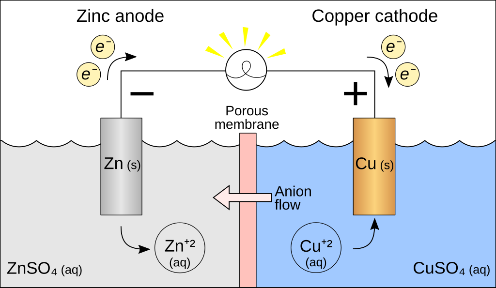
This is the first battery voltage, and you can see that this potential difference is just sitting there, and these electrons keep flowing. In sulfuric acid, the potential of an electron in zinc is  ; the fact that there is sulfuric acid changes these work function numbers. The charge of an electron is negative, so zinc has an electron and zinc has a potential energy of
  , an electron in the copper has a potential energy of
  .
.
This number is bigger, and so electrons will flow to the lower energy state, which is towards the copper, because electrons go against the potential, from low potential to high potential.
Instructor’s Note
Be careful here; we’re talking about electrons moving, and usually when you’re dealing with electronics, that’s what’s going on, but not always in a cell. For example, you can and often do have positive charges moving potassium ions, sodium ions, calcium ions, so those charges would move from high potential to low potential, because they’re positive, electrons go low to high, so you’ve got to think about what’s actually doing the moving.
Now, let’s go through and actually talk through how this thing keeps running. So, the gold-platinum, when we put them in contact, the electrons run across and they stopped, because it’s a buildup of charge and the repulsion stops the thing from going. Why does the zinc-copper keep going? Well, zinc dissolves in sulfuric acid, and you spit off a Zinc 2+ ion, which will eventually precipitate out a zinc sulfate. What does that leave behind in the metal? Electrons. Zinc 2+ popped off, now I’ve got two electrons, and now my zinc has a slight negative charge to it. Well, we just said that copper is the lower energy state, so the electrons would prefer to be in copper because it’s a lower energy state.
They go over and run through the wire because it is less resistance to run through the wire than to run through the solution. We would have the same problem that we did with our platinum-gold; we’d eventually build up charges on this side, and the whole thing would stop, but the solution comes in again. Because it’s sulfuric acid, there are these positive hydrogen ions sitting in there, and these electrons are attracted to these positive hydrogen ions and jump off. Which then forms a nice diatomic hydrogen, which bubbles out, and now we’re back where we started.
We have neutral-zinc, neutral-copper, and the whole thing can just keep going. So, we can continue moving these electrons across, and the reaction doesn’t stop because we come back to a neutral state each time, and we maintain a fixed potential difference.
Instructor’s Note
The reason this reaction keeps going is probably the number one thing that people miss in this unit.
Batteries have a fixed potential difference between the terminals; they don’t have a fixed current, and they don’t have a fixed power output. This is the number one thing people miss in this unit right here.
Instructor’s Note
The big takeaway is the battery has a fixed potential difference between its terminals; it does not maintain constant current, nor does it maintain constant power output.
Capacitors and Dielectrics
Based on Capacitors and Dielectrics from OpenStax.
Instructor’s Note
By the end of this section, you should know:
- A capacitor is a device used to store charge.
- The amount of charge a capacitor can store depends on two major factors—the voltage applied and the capacitor’s physical characteristics, such as its size.
- The capacitance
 is the amount of charge stored per volt, or
 .
.
- The capacitance of a parallel plate capacitor is
 , when the plates are separated by air or free space.
  is called the permittivity of free space.
 - A parallel plate capacitor with a dielectric between its plates has a capacitance given by
 ,
,
where  is the value for the material.
- The maximum electric field strength above which an insulating material begins to break down and conduct is called dielectric strength.
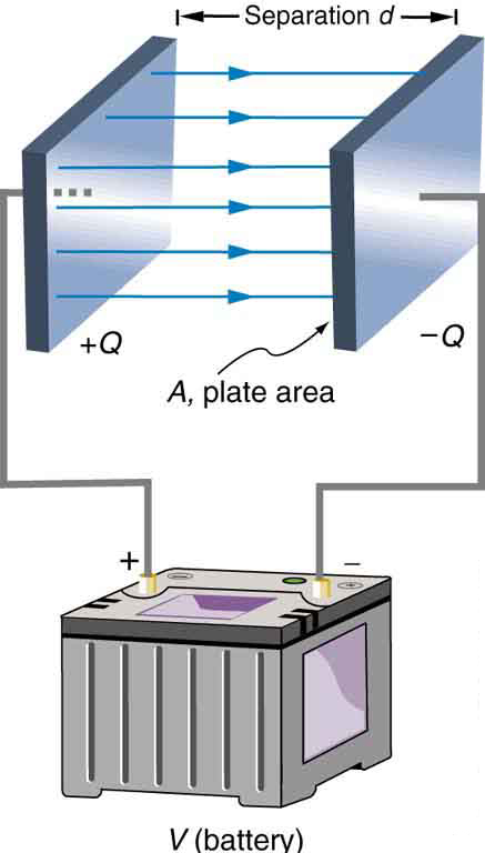
A capacitor is a device used to store electric charge. Capacitors have applications ranging from filtering static out of radio reception to energy storage in heart defibrillators. Typically, commercial capacitors have two conducting parts close to one another, but not touching, such as those in Figure 2. (Most of the time, an insulator is used between the two plates to provide separation—see the discussion on dielectrics below.) When battery terminals are connected to an initially uncharged capacitor, equal amounts of positive and negative charge,  and
and  , are separated into its two plates. The capacitor remains neutral overall, but we refer to it as storing a charge in this circumstance.
Capacitor
A capacitor is a device used to store electric charge.
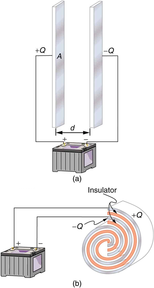 and on their two halves. (a) A parallel plate capacitor. (b) A rolled capacitor with an insulating material between its two conducting sheets.
The amount of charge a capacitor can store depends on two major factors—the voltage applied and the capacitor’s physical characteristics, such as its size.
The Amount of Charge Q A Capacitor Can Store
The amount of charge a capacitor can store depends on two major factors—the voltage applied and the capacitor’s physical characteristics, such as its size.
A system composed of two identical, parallel conducting plates separated by a distance, as in Figure 2, is called a parallel plate capacitor. It is easy to see the relationship between the voltage and the stored charge for a parallel plate capacitor, as shown in Figure 3. Each electric field line starts on an individual positive charge and ends on a negative one, so that there will be more field lines if there is more charge. (Drawing a single field line per charge is a convenience, only. We can draw many field lines for each charge, but the total number is proportional to the number of charges.) The electric field strength is, thus, directly proportional to .
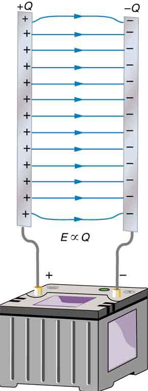
The field is proportional to the charge:
 ,
,
where the symbol  means “proportional to.” From the discussion in The Relationship between Electric and Potential and Electric Field, we know that the voltage across parallel plates is
  . Thus,
 .
.
It follows, then, that  , and conversely,
 .
.
This is true in general: The greater the voltage applied to any capacitor, the greater the charge stored in it.
Different capacitors will store different amounts of charge for the same applied voltage, depending on their physical characteristics. We define their capacitance to be such that the charge stored in a capacitor is proportional to . The charge stored in a capacitor is given by
 .
.
This equation expresses the two major factors affecting the amount of charge stored. Those factors are the physical characteristics of the capacitor. , and the voltage,  . Rearranging the equation, we see that capacitance is the amount of charge stored per volt, or
.
Capacitance
Capacitance is the amount of charge stored per volt, or
.
The unit of capacitance is the farad (F), named for Michael Faraday (1791–1867), an English scientist who contributed to the fields of electromagnetism and electrochemistry. Since capacitance is charge per unit voltage, we see that a farad is a coulomb per volt, or

A 1-farad capacitor would be able to store 1 coulomb (a very large amount of charge) with the application of only 1 volt. One farad is, thus, a very large capacitance. Typical capacitors range from fractions of a picofarad  to millifarads
  .
.
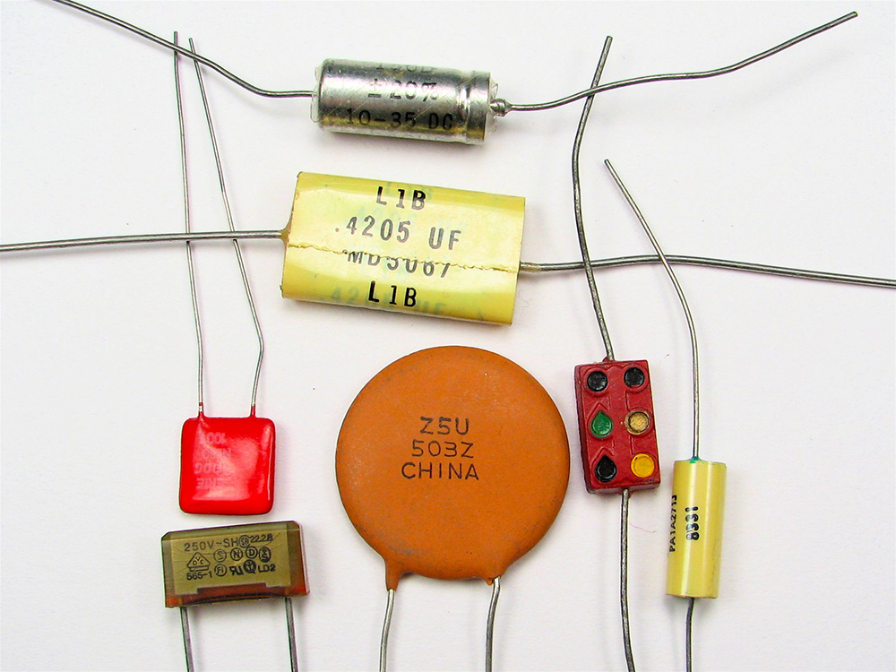
Figure 4 shows some common capacitors. Capacitors are primarily made of ceramic, glass, or plastic, depending on purpose and size. Insulating materials, called dielectrics, are commonly used in their construction, as discussed below.
Parallel Plate Capacitor
The parallel plate capacitor shown in Figure 5 has two identical conducting plates, each having a surface area  , separated by a distance
  (with no material between the plates). When a voltage is applied to the capacitor, it stores a charge , as shown. We can see how its capacitance depends on and by considering the characteristics of the Coulomb force. We know that like charges repel, unlike charges attract, and the force between charges decreases with distance. So it seems quite reasonable that the bigger the plates are, the more charge they can store—because the charges can spread out more. Thus should be greater for larger . Similarly, the closer the plates are together, the greater the attraction of the opposite charges on them. So should be greater for smaller .
 . Each plate has an area .
It can be shown that for a parallel plate capacitor, with vacuum (or the very similar air) between the plates, there are only two factors ( and ) that affect its capacitance . The capacitance of a parallel plate capacitor in equation form is given by
 .
.
The situation with something other than air is discussed below.
Capacitance of a Parallel Plate Capacitor with Vacuum or Air Between the Plates
is the area of one plate in square meters, and is the distance between the plates in meters. The constant  is the
  we have seen before. Now, we can write it in a new way as Farads/meters:
  . The small numerical value of
  is related to the large size of the farad. A parallel plate capacitor must have a large area to have a capacitance approaching a farad. (Note that the above equation is valid when the parallel plates are separated by air or free space. When another material is placed between the plates, the equation is modified, as discussed below.)
Capacitance and Charge Stored in a Parallel Plate Capacitor
a) What is the capacitance of a parallel plate capacitor with metal plates, each of area  , separated by 1.00 mm? (b) What charge is stored in this capacitor if a voltage of
  is applied to it?
Strategy
Finding the capacitance is a straightforward application of the equation  . Once is found, the charge stored can be found using the equation .
Solution for (a)
Entering the given values into the equation for the capacitance of a parallel plate capacitor yields

 .
.
Discussion for (a)
This small value for the capacitance indicates how difficult it is to make a device with a large capacitance. Special techniques help, such as using very large area thin foils placed close together.
Solution for (b)
The charge stored in any capacitor is given by the equation . Entering the known values into this equation gives

 .
.
Discussion for (b)
This charge is only slightly greater than those found in typical static electricity. Since air breaks down at about  , more charge cannot be stored on this capacitor by increasing the voltage.
Another interesting biological example dealing with electric potential is found in the cell’s plasma membrane. The membrane sets a cell off from its surroundings and also allows ions to selectively pass in and out of the cell. There is a potential difference across the membrane of about  . This is due to the mainly negatively charged ions in the cell and the predominance of positively charged sodium (
 ) ions outside. Things change when a nerve cell is stimulated. ions are allowed to pass through the membrane into the cell, producing a positive membrane potential—the nerve signal. The cell membrane is about 7 to 10 nm thick. An approximate value of the electric field across it is given by

This electric field is enough to cause a breakdown in air.
Dielectric
The previous example highlights the difficulty of storing a large amount of charge in capacitors. If is made smaller to produce a larger capacitance, then the maximum voltage must be reduced proportionally to avoid breakdown (since  ). An important solution to this difficulty is to put an insulating material, called a dielectric, between the plates of a capacitor and allow to be as small as possible. Not only does the smaller make the capacitance greater, but many insulators can withstand greater electric fields than air before breaking down.
There is another benefit to using a dielectric in a capacitor. As discussed in class during Unit III, the electric field in a material is smaller than in a vacuum due to the polarization of the material. In those analyses, we swapped  . We will do the same here. Thus, for a parallel plate capacitor filled with material, . Since essentially all materials have
  (everything is more polarizable than vacuum), the capacitance of a capacitor filled with material will be larger than one filled with air or vacuum.
Also, as discussed in class during Unit III, tables of materials typically do not list  but instead
  a factor called the dielectric constant
  . Values of the dielectric constant for various materials are given in the Table below. If Teflon is placed between the plates of the capacitor, as in the example after the table, then the capacitance is greater by the factor , which for Teflon is 2.1.
Take-Home Experiment: Building A Capacitor
How large a capacitor can you make using a chewing gum wrapper? The plates will be the aluminum foil, and the separation (dielectric) in between will be the paper.
Dielectric Constants and Dielectric Strengths for Various Materials at 20ºC
| Material | Dielectric constant κ | Dielectric strength (V/m) |
| Vacuum | 1.00000 | — |
| Air | 1.00059 | 3 X 10⁶ |
| Bakelite | 4.9 | 24 X 106 |
| Fused quartz | 3.78 | 8 X 10⁶ |
| Neoprene rubber | 6.7 | 12 X 106 |
| Nylon | 3.4 | 14 X 106 |
| Paper | 3.7 | 16 X 106 |
| Polystyrene | 2.56 | 24 X 106 |
| Pyrex glass | 5.6 | 14 X 106 |
| Silicon oil | 2.5 | 15 X 106 |
| Strontium titanate | 233 | 8 X 10⁶ |
| Teflon | 2.1 | 60 X 106 |
| Water | 80 | — |
Note also that the dielectric constant for air is very close to 1, so that air-filled capacitors act much like those with a vacuum between their plates, except that the air can become conductive if the electric field strength becomes too great. (Recall that  .) Also shown in this table are maximum electric field strengths in V/m, called dielectric strengths, for several materials. These are the fields above which the material begins to break down and conduct. The dielectric strength imposes a limit on the voltage that can be applied for a given plate separation. For instance, in Example, the separation is 1.00 mm, and so the voltage limit for air is


 .
.
However, the limit for a 1.00 mm separation filled with Teflon is 60,000 V, since the dielectric strength of Teflon is  . So the same capacitor filled with Teflon has a greater capacitance and can be subjected to a much greater voltage. Using the capacitance we calculated in the above example for the air-filled parallel plate capacitor, we find that the Teflon-filled capacitor can store a maximum charge of


This is 42 times the charge of the same air-filled capacitor.
Dielectric Strength
The maximum electric field strength above which an insulating material begins to break down and conduct is called its dielectric strength.
PhET Explorations: Capacitor Lab
Explore how a capacitor works! Change the size of the plates and add a dielectric to see the effect on capacitance. Change the voltage and see charges built up on the plates. Observe the electric field in the capacitor. Measure the voltage and the electric field.
Ohm’s Law: Resistance and Simple Circuits
Derived from Ohm’s Law: Resistance and Simple Circuits by OpenStax
What drives current? We can think of various devices—such as batteries, generators, wall outlets, and so on—which are necessary to maintain a current. All such devices create a potential difference and are loosely referred to as voltage sources. When a voltage source is connected to a conductor, it applies a potential difference that creates an electric field. The electric field, in turn, exerts force on charges, causing current.
Ohm’s Law
The current that flows through most substances is directly proportional to the voltage applied to it. The German physicist Georg Simon Ohm (1787–1854) was the first to demonstrate experimentally that the current in a metal wire is directly proportional to the voltage applied:

This important relationship is known as Ohm’s law. It can be viewed as a cause-and-effect relationship, with voltage the cause and current the effect. This is an empirical law like that for friction—an experimentally observed phenomenon. Such a linear relationship doesn’t always occur.
Resistance and Simple Circuits
If voltage drives current, what impedes it? The electric property that impedes current (crudely similar to friction and air resistance) is called resistance  . Collisions of moving charges with atoms and molecules in a substance transfer energy to the substance and limit current. Resistance is defined as inversely proportional to current, or

Thus, for example, current is cut in half if resistance doubles. Combining the relationships of current to voltage and current to resistance gives
 .
.
This relationship is also called Ohm’s law. Ohm’s law in this form really defines resistance for certain materials. Ohm’s law (like Hooke’s law) is not universally valid. The many substances for which Ohm’s law holds are called ohmic. These include good conductors like copper and aluminum, and some poor conductors under certain circumstances. Ohmic materials have a resistance that is independent of voltage and the current  . An object that has simple resistance is called a resistor, even if its resistance is small. The unit for resistance is an ohm and is given the symbol
  (upper case Greek omega). Rearranging
  gives
gives  and so the units of resistance are 1 ohm = 1 volt per ampere:

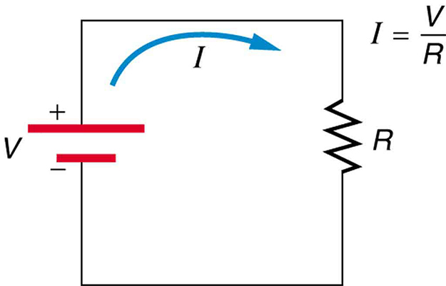
Figure 1 shows the schematic for a simple circuit. A simple circuit has a single voltage source and a single resistor. The wires connecting the voltage source to the resistor can be assumed to have negligible resistance, or their resistance can be included in .
Calculating Resistance: An Automobile Headlight
What is the resistance of an automobile headlight through which 2.50 A flows when 12.0 V is applied to it?
Strategy
We can rearrange Ohm’s law as stated by and use it to find the resistance.
Solution
Rearranging and substituting known values gives

Discussion
This is a relatively small resistance, but it is larger than the cold resistance of the headlight. As we shall see in Resistance and Resistivity below, resistance usually increases with temperature, and so the bulb has a lower resistance when it is first switched on and will draw considerably more current during its brief warm-up period.
Resistances range over many orders of magnitude. Some ceramic insulators, such as those used to support power lines, have resistances of  or more. A dry person may have a hand-to-foot resistance of
  , whereas the resistance of the human heart is about
  . A meter-long piece of large-diameter copper wire may have a resistance of
  , and superconductors have no resistance at all (they are non-ohmic). Resistance is related to the shape of an object and the material of which it is composed, as will be seen in Resistance and Resistivity below.
Additional insight is gained by solving for , yielding

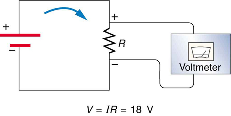
This expression for can be interpreted as the voltage drop across a resistor produced by the flow of current . The phrase  drop is often used for this voltage. For instance, the headlight in the automobile headlight example above has an drop of 12.0 V. If voltage is measured at various points in a circuit, it will be seen to increase at the voltage source and decrease at the resistor. Voltage is similar to fluid pressure. The voltage source is like a pump, creating a pressure difference, causing current—the flow of charge. The resistor is like a pipe that reduces pressure and limits flow because of its resistance. Conservation of energy has important consequences here. The voltage source supplies energy (causing an electric field and a current), and the resistor converts it to another form (such as thermal energy). In a simple circuit (one with a single simple resistor), the voltage supplied by the source equals the voltage drop across the resistor, since
  , and the same
  flows through each. Thus, the energy supplied by the voltage source and the energy converted by the resistor are equal. (See Figure 2.)
Making Connections: Conservation of Energy
In a simple electrical circuit, the sole resistor converts energy supplied by the source into another form. Conservation of energy is evidenced here by the fact that all of the energy supplied by the source is converted to another form by the resistor alone. We will find that conservation of energy has other important applications in circuits and is a powerful tool in circuit analysis.
PhET Explorations: Ohm’s Law
See how the equation form of Ohm’s law relates to a simple circuit. Adjust the voltage and resistance, and see the current change according to Ohm’s law. The sizes of the symbols in the equation change to match the circuit diagram.
Section Summary
- A simple circuit is one in which there is a single voltage source and a single resistance.
- One statement of Ohm’s law gives the relationship between current , voltage , and resistance in a simple circuit to be .
- Resistance has units of ohms (), related to volts and amperes by
 .
. - There is a voltage or drop across a resistor, caused by the current flowing through it, given by .
Resistance and Resistivity
Derived from Resistance and Resistivity by OpenStax
Instructor’s Note
For this section, I am NOT expecting you to remember the formula exactly. What I want you to know is that resistance increases with length (more atoms to run into), decreases with area, and is dependent upon the resistivity of the material.
Material and Shape Dependence of Resistance
The resistance of an object depends on its shape and the material of which it is composed. The cylindrical resistor in Figure 1 is easy to analyze, and, by so doing, we can gain insight into the resistance of more complicated shapes. As you might expect, the cylinder’s electric resistance is directly proportional to its length  , similar to the resistance of a pipe to fluid flow. The longer the cylinder, the more collisions charges will make with its atoms. The greater the diameter of the cylinder, the more current it can carry (again, similar to the flow of fluid through a pipe). In fact, is inversely proportional to the cylinder’s cross-sectional area .
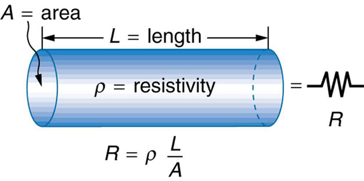
For a given shape, the resistance depends on the material of which the object is composed. Different materials offer different resistance to the flow of charge. We define the resistivity  of a substance so that the resistance of an object is directly proportional to . Resistivity is an intrinsic property of a material, independent of its shape or size. The resistance of a uniform cylinder of length , of cross-sectional area , and made of a material with resistivity , is

The table below gives representative values of . The materials listed in the table are separated into categories of conductors, semiconductors, and insulators, based on broad groupings of resistivities. Conductors have the smallest resistivities, and insulators have the largest; semiconductors have intermediate resistivities. Conductors have varying but large free charge densities, whereas most charges in insulators are bound to atoms and are not free to move. Semiconductors are intermediate, having far fewer free charges than conductors, but having properties that make the number of free charges depend strongly on the type and amount of impurities in the semiconductor. These unique properties of semiconductors are put to use in modern electronics, as will be explored in later chapters.
| Material | Resistivity  |
| Conductors | |
| Silver |  |
| Copper |  |
| Gold |  |
| Aluminum |  |
| Tungsten |  |
| Iron |  |
| Platinum |  |
| Steel |  |
| Lead |  |
| Manganin (Cu, Mn, Ni alloy) |  |
| Constantan (Cu, Ni alloy) |  |
| Mercury |  |
| Nichrome (Ni, Fe, Cr alloy) |  |
| Semiconductors | |
| Carbon (pure) |  |
| Carbon |  |
| Germanium (pure) |  |
| Germanium |  |
| Silicon (pure) |  |
| Silicon |  |
| Insulators | |
| Amber |  |
| Glass |  |
| Lucite |  |
| Mica |  |
| Quartz (fused) |  |
| Rubber (hard) |  |
| Sulfur |  |
| Teflon | |
| Wood |  |
Resistivity of Various materials at 20ºC
Calculating Resistor Diameter: A Headlight Filament
A car headlight filament is made of tungsten and has a cold resistance of  . If the filament is a cylinder 4.00 cm long (it may be coiled to save space), what is its diameter?
Strategy
We can rearrange the equation  to find the cross-sectional area of the filament from the given information. Then its diameter can be found by assuming it has a circular cross-section.
Solution
The cross-sectional area, found by rearranging the expression for the resistance of a cylinder given in  , is
, is
 .
.
Substituting the given values, and taking from the table, yields

 .
.
The area of a circle is related to its diameter  by
by

Solving for the diameter , and substituting the value found for , gives


Discussion
The diameter is just under a tenth of a millimeter. It is quoted to only two digits, because is known to only two digits.
Temperature Variation of Resistance
The resistivity of all materials depends on temperature. Some even become superconductors (zero resistivity) at very low temperatures. (See Figure 2.) Conversely, the resistivity of conductors increases with increasing temperature. Since the atoms vibrate more rapidly and over larger distances at higher temperatures, the electrons moving through a metal make more collisions, effectively making the resistivity higher. Semiconductors, on the other hand, have resistivities that decrease with increasing temperature. They become better conductors at higher temperatures because increased thermal agitation increases the number of free charges available to carry current. This property of decreasing with temperature is also related to the type and amount of impurities present in the semiconductors.
The resistance of an object also depends on temperature, since  is directly proportional to . For a cylinder we know
  , and so, if and do not change greatly with temperature, will have the same temperature dependence as . (Examination of the coefficients of linear expansion shows them to be about two orders of magnitude less than typical temperature coefficients of resistivity, and so the effect of temperature on and is about two orders of magnitude less than on .) Numerous thermometers are based on the effect of temperature on resistance. (See Figure 2.) One of the most common is the thermistor, a semiconductor crystal with a strong temperature dependence, the resistance of which is measured to obtain its temperature. The device is small, so it quickly comes into thermal equilibrium with the part of a person it touches.

PhET Explorations: Resistance in a Wire
Learn about the physics of resistance in a wire. Change its resistivity, length, and area to see how they affect the wire’s resistance. The sizes of the symbols in the equation change along with the diagram of a wire.
Section Summary
- The resistance increases with length and decreases with cross sectional area.
- The resistance is also dependent on the resistivity of the material.
- Values of fall into three groups—conductors, semiconductors, and insulators.
- For a metal, resistivity, and therefore resistance, increases with temperature as the nuclei are jiggling around more, resulting in more collisions as the electrons try to travel.
