
14 Producing Images with Geometric Optics
Terminology of Images and Optical Elements

Instructor’s Note
By the end of this section you should:
- Be able to define several terms associated with images and optics.
- Know and apply the sign conventions associated with objects and images in optics.
An is any lens or mirror. A few examples include the lens in your eye that you’re using to read this or the aforementioned shaving or makeup mirror that many people have to help them get ready in the morning, it makes your face look a little bigger than it is. The lens or the mirror are examples of optical elements. Anything that’s a lens or a mirror is an optical element.
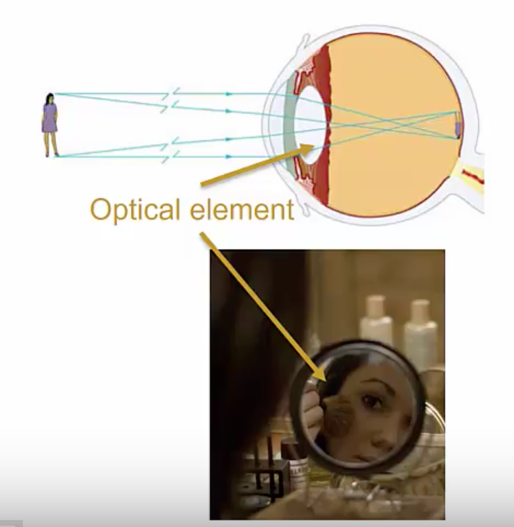
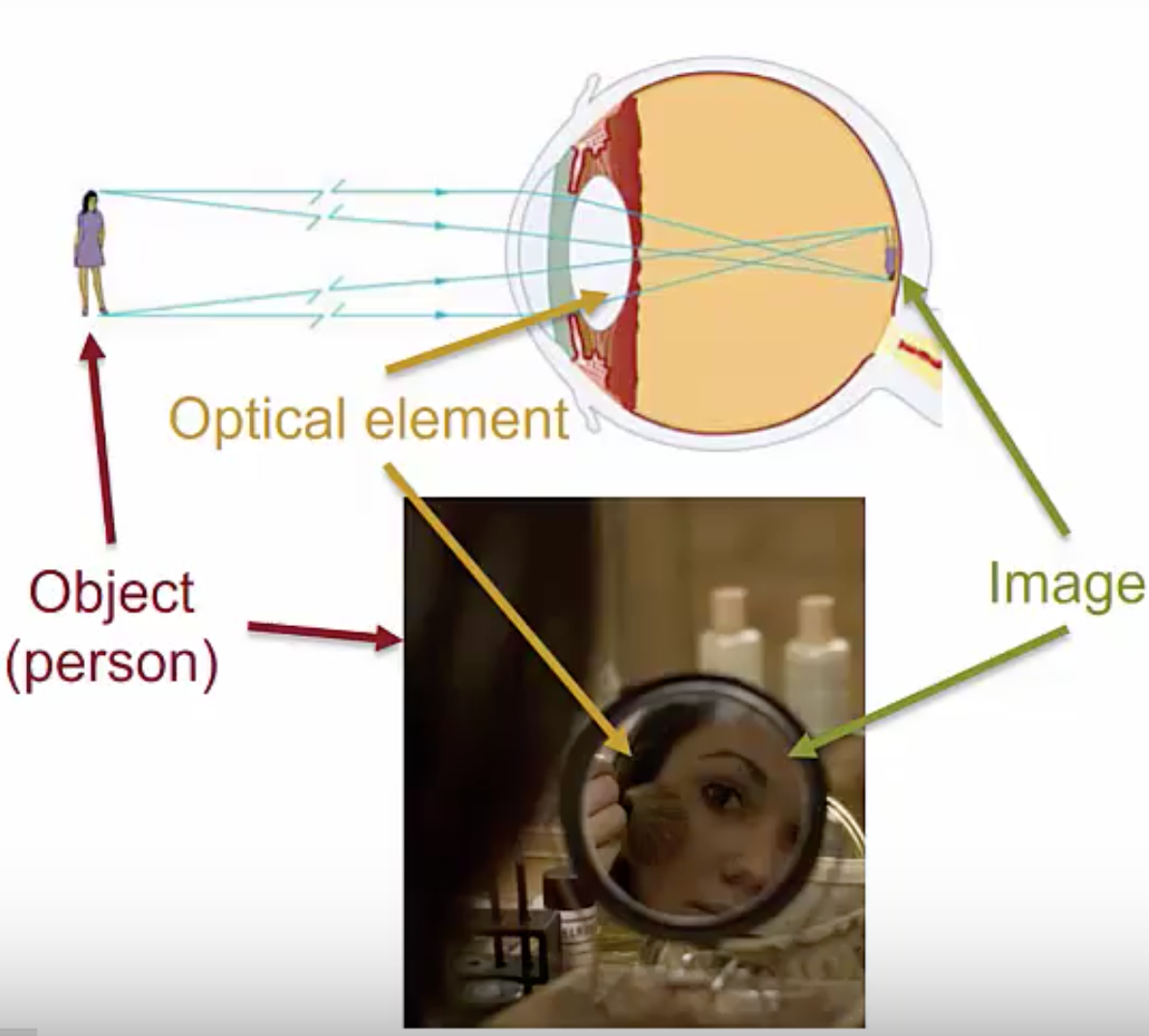
Optical elements or combinations of them can be used to make . An image is the apparent reproduction of an object formed by an optical element, or a collection of them, through the reflection and/or refraction of light. In these two examples, the person is our object, and the images are the image on the back of your retina formed by your eyeball, or the image of your reflection in the mirror.
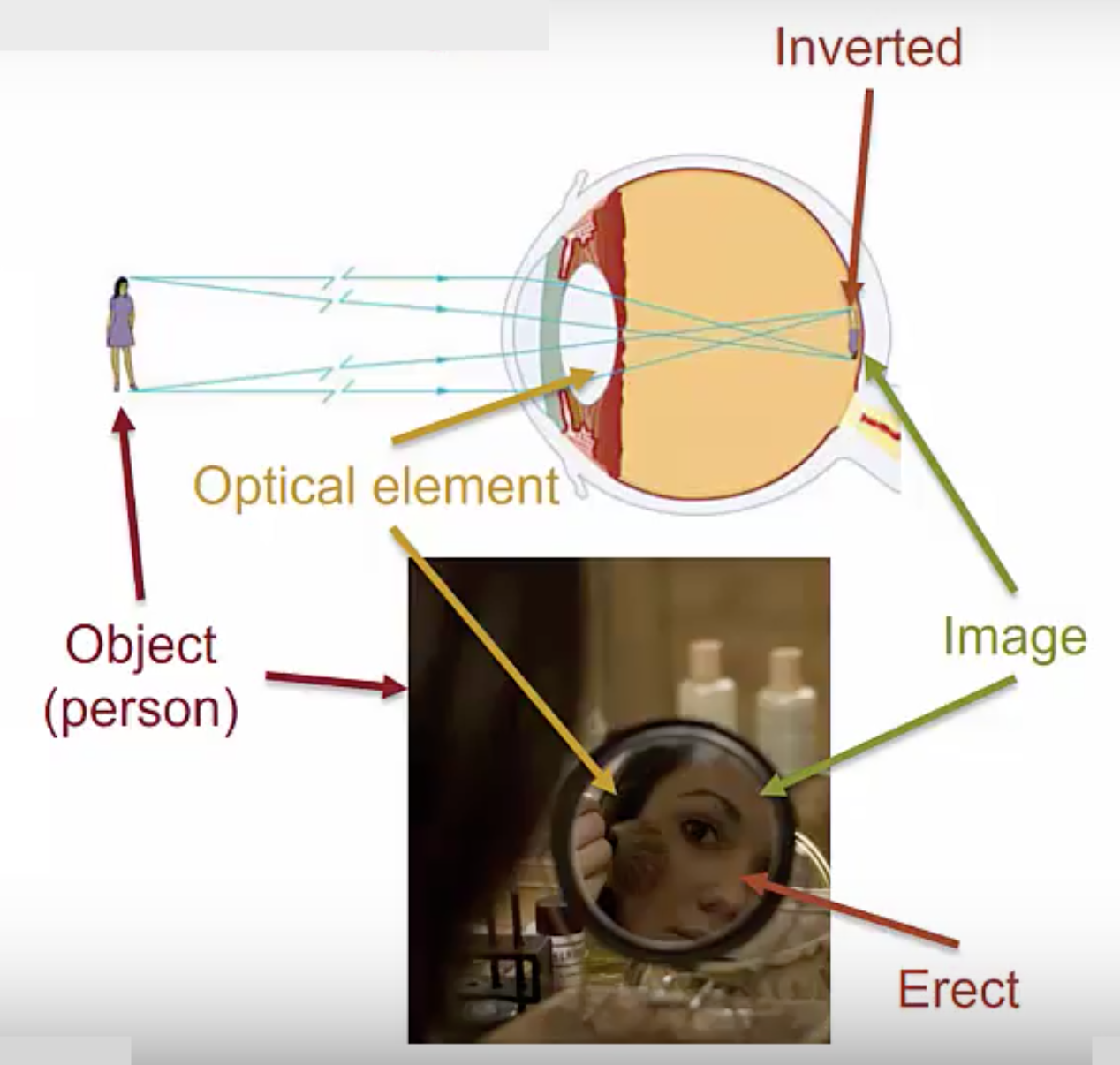
Images can either be , with the same orientation as the object, or, upside down with respect to the object. In the makeup mirror, your face is right-side up, and so the image is erect. The images on your retina are actually upside down; your brain corrects them to put them right side up, and this is an example of an inverted image.
Before we move on to talk about image and object distances, we need to introduce two more terms: the and the .
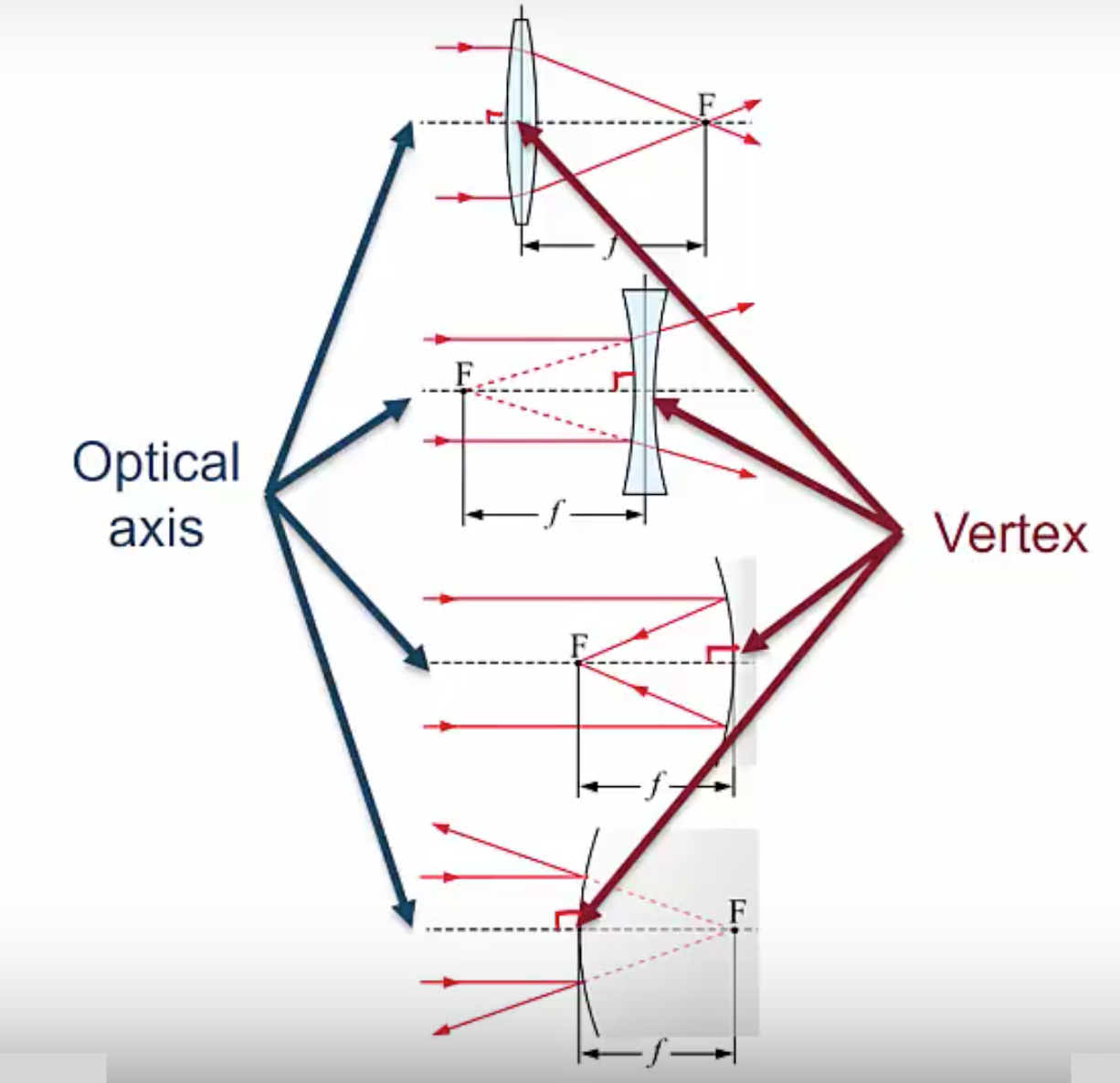
The is an imaginary line that passes through the optical element in a way that’s perpendicular to it. Below, we have a converging lens at the top, with a diverging lens below that, with a converging mirror below that, and a diverging mirror at the bottom. This dashed line that always meets the lens or mirror perpendicular is what we call the optical axis.
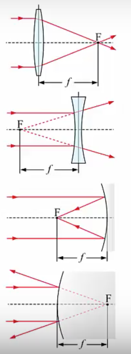
Looking at a few examples, we can see that the optical axis meets the lens perpendicular here in the middle, same for the diverging lens. Moving on to the mirrors, we see the optical axis meets the two mirrors in a way that’s perpendicular. The point where the optical axis meets the optical element is called the vertex.
The reason we needed these terms is because the image distance  and object distance
  are measured along the optical axis from the vertex and these distances have signs that can be positive or negative and the sides are relative to the path of the light if the object is on the same side as the incoming light, then the object distance will be positive, otherwise the object distance is negative. If the image is on the same side as the outgoing light, then the image distance is positive; otherwise, the image distance is negative. Note that for our lens, the incoming and outgoing sides are different; light passes through a lens, so the light comes in one side and goes out the other. For a mirror, on the other hand, the incoming and outgoing sides are the same: light bounces off a mirror. These may seem like a rather convoluted set of rules, but it turns out that this is actually the simplest set of rules that works for all lenses and mirrors, so any other set of rules you might try to come up with will necessarily be more complicated.
Let’s employ these sign conventions in the terms of two examples, one with a lens and one with a mirror.
To begin with a lens, let’s say you’re looking at a person about 10 meters away. Your eye produces an image on the back of your retina, which is about an inch behind the lens of your eye or 2.5 centimeters; what are the image and object distances, including the signs?
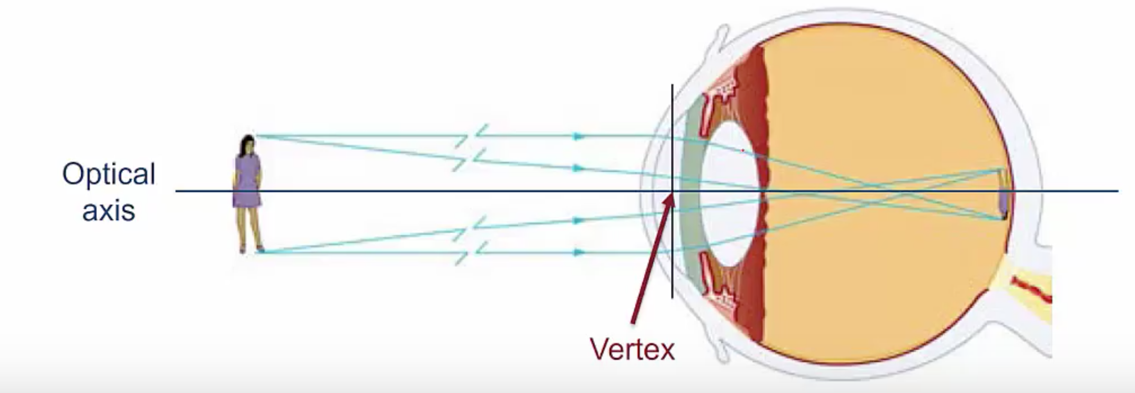
First, we define our optical axis, passing through the lens. You’ll notice the light is bending here, so that’s what we’re actually defining as our lens. The point where the optical axis meets the lens is the vertex; this is the point from which we are measuring our image and object distances. Now the person, of course, doesn’t shine off by their own light, but from light bouncing off of them, which means the light is coming from the left.
Because the person is on the same side as where the light is coming from, the object distance is going to be positive. Now, we also know the person is 10 meters away, so we would say the object distance is 10 meters. For the image on the back of your retina, the image is 0.25 centimeters past the vertex on the side where the light is going out, which means the image distance is also positive, leading to an image distance of 2.5 centimeters.
Now let’s look at an example with a mirror. A can of shaving cream sits 30 centimeters in front of a flat plane mirror, like you have in your bathroom. You see the image of the shaving can apparently 30 centimeters behind the mirror. What are the image distances, , and the object distance, ?
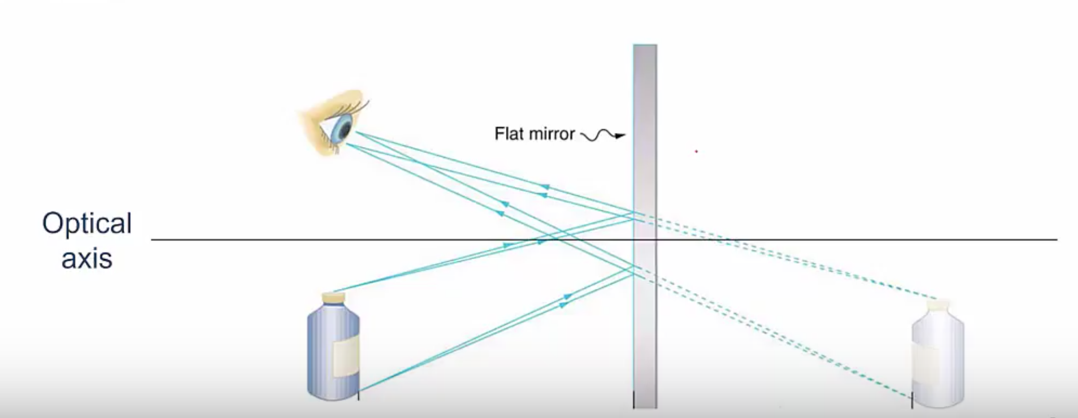
Once again, we define our optical axis so that it meets the mirror perpendicular. The can does not shine by its own light but from light bouncing off of it, so the light is coming from the left, which means the object is on the same side as the incoming light, which means the object distance is positive and 30 centimeters, so is 30 centimeters.
The image, on the other hand, is not on the side of the outgoing light because the light bounces off the mirror and back the way it came from. The image is on the side opposite the outgoing and so the image distance, , is actually – 30 centimeters.
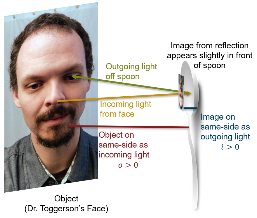
One more practice – Looking into a Spoon
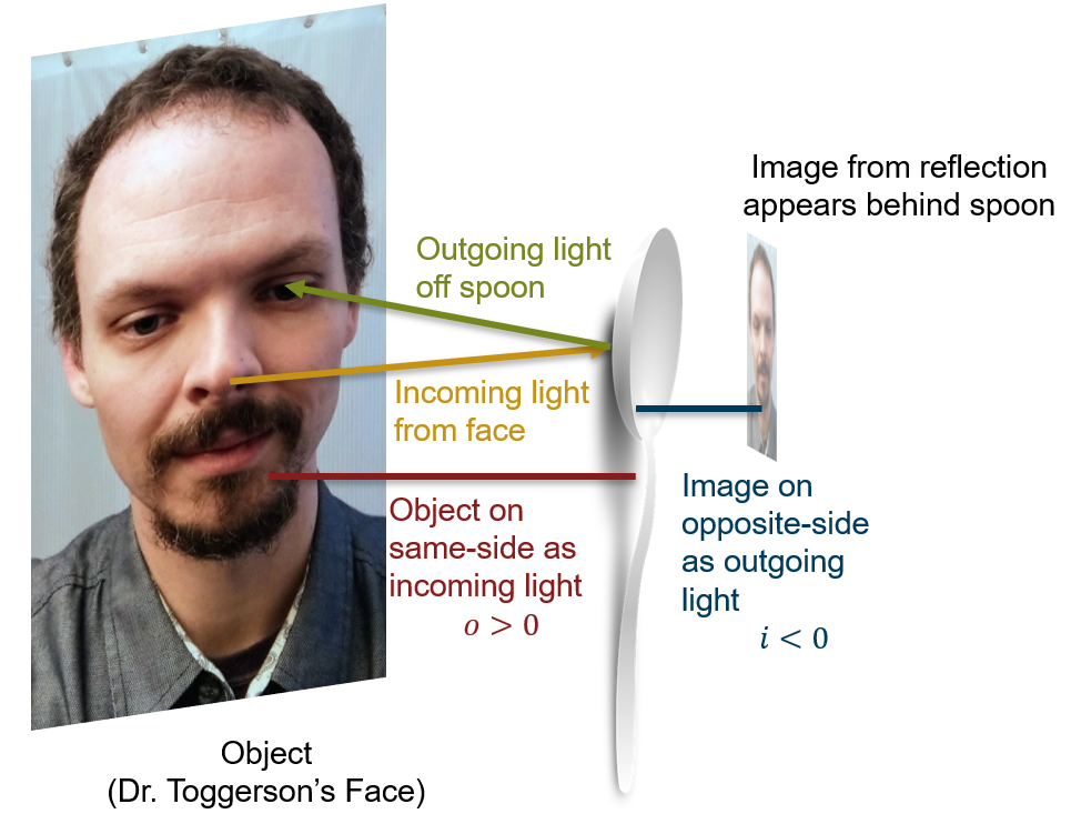
Go get a metal spoon and look into each side. Pictures from Dr. Toggerson are below, but this really works better if you do it yourself. If you look in the back, as in Figure 8a, your image seems to be behind the spoon. In contrast, if you look carefully at the inside, as in Figure 8b, your image seems to hover in front of the spoon (take a piece of paper or a toothpick and try to poke it, and you will see what I mean).
What are the sign conventions for and in these cases?
 |
 |
Solution – back of spoon:
For the back of the spoon:
- The light is coming off your face and hitting the spoon, thus the object is on the same side as the incoming light:
 .
. - The image is on the opposite side as the outgoing light: the light bounces back towards you and does not go behind the spoon. Thus

Solution – Front of spoon
If you are looking in a spoon carefully, you will see that the image appears to hover in front of it. As such:
- The object is still on the same side as the incoming light:
- The image is now on the same side as the outgoing light:

Discussion:
I know that these rules seem odd and obtuse and that it will be tempting to make up your own rules: DON’T. These rules work for all situations. You just need to think about the perspective of where the light is traveling.
Section Summary
- An optical element is a lens or a mirror.
- An image is the apparent reproduction of an object, formed by an optical element or a collection of them, through the refraction or reflection of light.
- Images can either be erect, right side up, or inverted, upside down.
- The optical axis is an imaginary line that passes through the optical element perpendicular to it.
- The point where this optical axis meets the optical element is called the vertex, which is at the center of a lens or the surface of a mirror.
- Image and object distances are measured along the optical axis from the vertex, and the signs of the image distance, , and the object distance, , are relative to the path of light.
- If the object is on the same size as the incoming light, then the object distance is positive.
- If the image is on the same side as the outgoing light, then the image distance is positive.
- For a lens, the incoming and outgoing sides are different because the light goes through it.
- For a mirror, on the other hand, the incoming and outgoing sides are the same because the light bounces.
Problem 15: Sign conventions for object and image distances: objects and images on opposite sides of the optical element.
Problem 16: Sign conventions for object and image distances: objects and images on the same side of the optical element.
Magnification of Images
Instructor’s Note
Your quiz will cover:
- Given two of magnification, image height, and object height, find the third
- Know that the magnification of an inverted image is negative
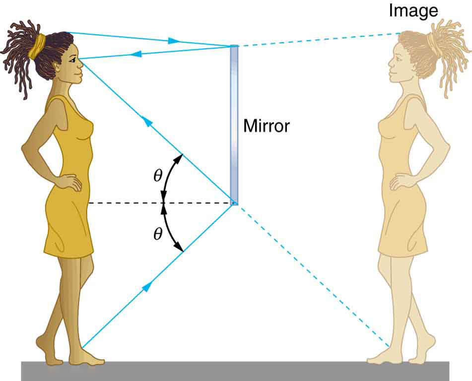
When you look in a flat bathroom mirror, your image is the same height as you are. Look at the picture of Dr. Toggerson below in Figure 1. Figure 1a is taken 20cm in front of a mirror (you can see the camera). The image seems to be exactly the same distance, 20cm, behind the mirror as Dr. Toggerson is in front of it. This is shown diagrammatically in Figure 2, where the woman is the same distance in front of the mirror as her reflection is behind it; also, she and her reflection are the same height. This is confirmed with Figure 1b, which was taken with the camera at 40cm from Dr. Toggerson’s face as the mirror. The height of Dr. Toggerson’s face is the same in Figures 1a and 1b. In contrast, look at Figure 3a below, which is taken in the back of a spoon, Dr. Toggerson’s face is much smaller, about 2.5 cm (1 in, it fits on the spoon!). Similarly, in Figure 3b, looking at the inside of a spoon, his image, while larger than in the back of the spoon, is again smaller than his face. Moreover, the image on the inside of the spoon is upside down! The flat mirror and the back of the spoon have images, while the image formed by the inside of the spoon is . The different heights are covered by the concept of magnification. Magnification is simply the ratio of image height to object height:

where  is the height of the image and
  is the height of the object. As a ratio of heights, magnification is, itself, unit-less and just represents how many times bigger or smaller the image is than the object. One last note: if the image is inverted, we say that its height is negative. Thus, inverted images have negative magnification. Hopefully, this choice seems reasonable.
 |
 |
|
|
|
Magnification in a Flat Mirror
As we have seen, in a flat mirror, your image is the same height as you. What is the magnification of a flat mirror?
Solution:
Well, we know the definition of magnification:
Let’s use Dr. Toggerson as our example. Dr. Toggerson is about 1.7 m tall, which means his reflection in a flat mirror is also 1.7 m tall. Using these values, we see:

Discussion:
Note, the answer is just 1, no units!
Magnification in a Spoon
Dr. Toggerson is 1.7 m tall. His image in the back of a spoon is about 0.5 cm. The image in the front of the spoon is about 1 cm. What is the magnification of each?
Solution for the back of the spoon:
Again, we know the definition of magnification:
All we need to do is substitute the known values. However, for the result to be unit-less, we need to express both the image height and the object height in the same units; it doesn’t matter what units we use, they just have to be the same. Let’s use meters:

The image is 0.3% of Dr. Toggerson’s height!
Solution for the front of the spoon:
The procedure is essentially the same; the only difference this time is that the image height should be considered to be negative  as the image is inverted. Also, for fun, lets work in cm this time:


The magnification is negative, again representing the fact that the image is inverted.
Problem 17: What characterizes an object with a negative magnification?
Problem 18: Calculating magnification of a gemstone.
Introduction to Lenses
Instructor’s Note
By the end of this section, you should:
- Describe what a lens is and describe the two kinds of lenses: converging and diverging.
- Describe what each type of lens does and how these two types of lenses are different.
- Define focal length and focal point for any lens.
- Describe the idea behind the thin lens approximation.
What is a lens?
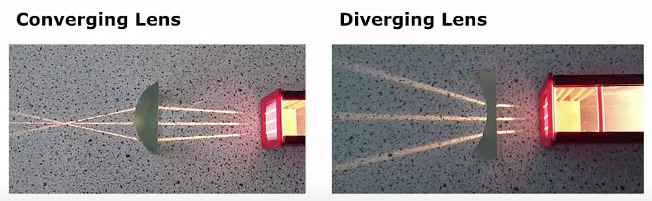
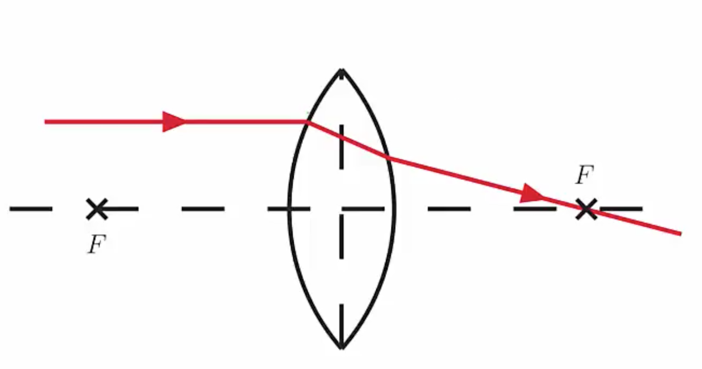
A lens is a piece of transparent material designed to take incoming parallel photons and can bend them to a point, which we call a converging lens, pictured below, where incoming parallel photons from the right pass into the lens and converge to a point on the left.
A common application that you might have experienced with this is taking a regular magnifying glass and focusing the sun’s light to a point. The incoming light from the sun is effectively parallel, and the magnifying glass focuses it to a point.
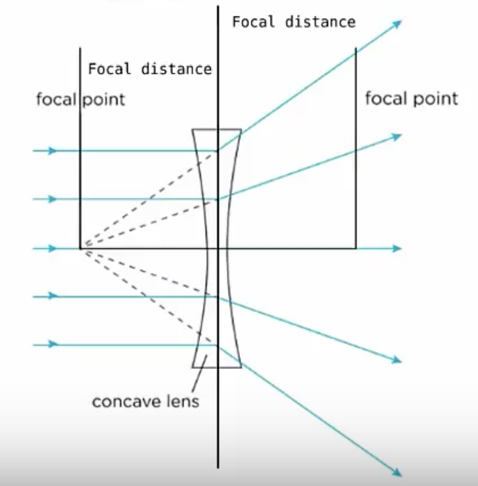
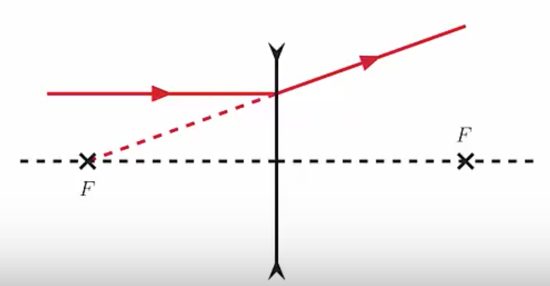
The other thing a lens can do is spread incoming parallel photons as if they came from a point. This is known as a diverging lens. When the light passes through the lens, the light spreads out, and from the left side, it appears that the light originated at this point.
A common application of diverging lenses is on your face if you happen to be nearsighted: if you’re nearsighted, the glasses you’re wearing are a diverging lens.
Let’s talk a little bit about the properties of converging versus diverging lenses. Converging lenses are always thicker at the center than at the edges. On the flip side, diverging lenses are thicker at the edges than they are in the middle.
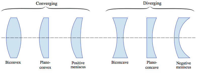
Instructor’s Note
You don’t need to know the names of these particular shapes; you just need to know that converging lenses are thicker at the middle and diverging lenses are thicker at the edges.
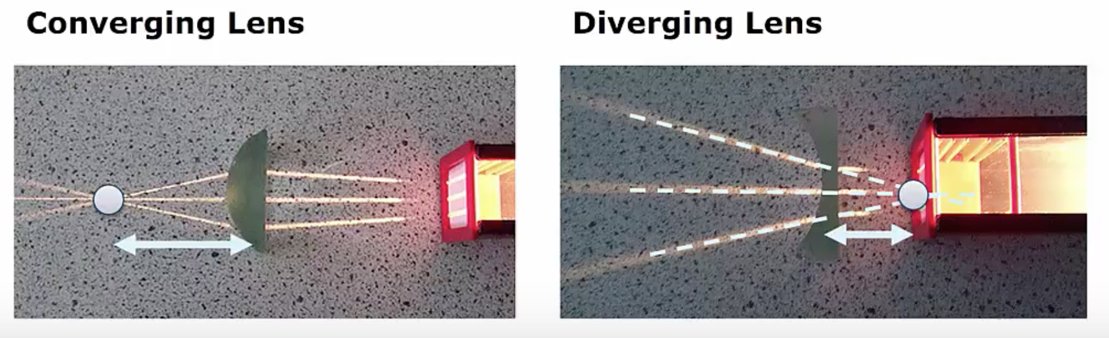
Let’s move on to probably the most important property of a lens, the focal length and focal points. Here are our two lenses, the converging lens on the left and the diverging lens on the right. In both cases, you can see the light coming from the right passing through the lens on its way to the left.
The focal point is defined as the point at which the parallel photons either converge or appear to. Meanwhile, the focal length is the distance from the center of the lens to that point; because the focal length is a distance, the unit of focal length is meters.
For the converging lens, the point where the photons appear to intersect is the focal point. Meanwhile, for the diverging lens, we trace the rays back through the lens, and they appear to come from this point behind the lens; this is the focal point of a diverging lens.
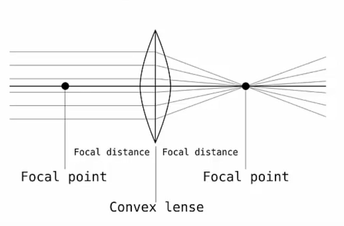
We always measure the focal length from the center of the lens to the focal point, so you can see it here on the left for the converging lens and here on the right for the diverging lens. Every lens has only one focal length, but two focal points with one on each side.
Below, we can see the full setup for a converging lens. In this case, we’ve got the light coming in from the left and moving towards the right. We can see the two different focal points, one on each side of the lens, each a focal length from the center of the lens, and these two focal lengths are the same.
Similarly, for a diverging lens, we have two focal points: one on each side of the lens, each at a distance of the focal length from the center. The convention is that focal lengths for converging lenses are positive, while diverging lenses have negative focal lengths.
Instructor’s Note
In addition to a lot of vocabulary, optics also has a lot of sign conventions that I am expecting you to learn from this prep. There is a set of flashcards on Quizlet to help you.
Finally, let’s move on to the thin lens approximation. In a real lens, light will bend at each surface. It will bend as it goes from the air to glass, or whatever material the lens is made of, and then it will bend again by Snell’s law when the light moves from the glass back into the air.
However, we will assume that the lens is very thin. What do we mean by thin? We mean that the thickness of the lens is very small relative to the focal length. Under this approximation, it’s essentially as if all the light bending happens at the center. Now, this is not actually what happens; remember, the light does bend at each interface, air to glass and glass to air. However, if the lens is very thin, these two interfaces are so close together and so close to the center of the lens that we can ignore it.
Section Summary
- A lens is a transparent material that either bends parallel light toward a focal point in the case of a converging lens or bends the light away in such a way that it appears to originate from a point in the case of a diverging lens.
- Each lens has two focal points: one on each side of the lens, because we can, of course, send the light through the lens either from the left or from the right, and we’ve seen examples of light traveling both ways.
- Focal lengths for converging lenses are positive, and focal lengths for diverging lenses are, by convention, negative.
- In reality, light bends at each surface of the lens; however, if the lens is thin relative to the focal length, then we can treat all of the bending as if it is happening at the center of the lens. This is known as the thin lens approximation.
Lenses Specifically as Applied to the Human Eye
Instructor’s Note
In this section, you will return to the overview of the human eye that was introduced in the motivation for this unit. Here, you will begin to see how to connect what you may know from biology to what you have just read about lenses. What we expect you to know from this reading is:
- Most of the focusing of the eye does NOT happen at the lens, but instead happens at the air-to-water interface at the front of the cornea.
- The lens of the eye provides the fine-tuning of the focus to get the image distance to land on the retina.
- The cornea and lens together act as a single lens system.
- In medicine, people often talk of the of a lens: this is 1/f where f is the . Your glasses prescription, if you have one, is listed in diopters.
- Note that although this power shares the same name as the power discussed in Unit I, it is a different quantity (Homonyms – they are not just for English!)
- The unit of optical power is 1/m or a diopter.
- This is consistent, as a lens with a shorter focal length bends the light more strongly and has a higher power.
The eye is remarkable in how it forms images and in the richness of detail and color it can detect. However, our eyes often need some correction to reach what is called “normal” vision. Actually, normal vision should be called “ideal” vision because nearly one-half of the human population requires some sort of eyesight correction, so requiring glasses is by no means “abnormal.” Image formation by our eyes and common vision correction can be analyzed with the optics discussed earlier in this chapter.
Figure 1 shows the basic anatomy of the eye. The cornea and lens form a system that, to a good approximation, acts as a single thin lens. For clear vision, a real image must be projected onto the light-sensitive retina, which lies a fixed distance from the lens. The flexible lens of the eye allows it to adjust the radius of curvature of the lens to produce an image on the retina for objects at different distances. The center of the image falls on the fovea, which has the greatest density of light receptors and the greatest acuity (sharpness) in the visual field. The variable opening (i.e., the pupil) of the eye, along with chemical adaptation, allows the eye to detect light intensities from the lowest observable to 1010 times greater (without damage). This is an incredible range of detection. Processing of visual nerve impulses begins with interconnections in the retina and continues in the brain. The optic nerve conveys the signals received by the eye to the brain.

The indices of refraction in the eye are crucial to its ability to form images. Table 1 lists the indices of refraction relevant to the eye. The biggest change in the index of refraction, which is where the light rays are most bent, occurs at the air-cornea interface rather than at the aqueous humor-lens interface. The ray diagram in Figure 2 shows image formation by the cornea and lens of the eye. The cornea, which is itself a converging lens with a focal length of approximately 2.3 cm, provides most of the focusing power of the eye. The lens, which is a converging lens with a focal length of about 6.4 cm, provides the finer focus needed to produce a clear image on the retina. The cornea and lens can be treated as a single thin lens, even though the light rays pass through several layers of material (such as cornea, aqueous humor, several layers in the lens, and vitreous humor), changing direction at each interface. The image formed is much like the one produced by a single convex lens (i.e., a real, inverted image). Although images formed in the eye are inverted, the brain inverts them once more to make them seem upright.
| Material | Index of Refraction |
|---|---|
| Water | 1.33 |
| Air | 1.0 |
| Cornea | 1.38 |
| Aqueous humor | 1.34 |
| Lens | 1.41* |
| Vitreous humor | 1.34 |

 must equal the lens-to-retina distance. Because the lens-to-retina distance does not change, the image distance must be the same for objects at all distances. The ciliary muscles adjust the shape of the eye lens for focusing on nearby or far objects. By changing the shape of the eye lens, the eye changes the focal length of the lens. This mechanism of the eye is called accommodation.
The nearest point an object can be placed so that the eye can form a clear image on the retina is called the near point of the eye. Similarly, the far point is the farthest distance at which an object is clearly visible. A person with normal vision can see objects clearly at distances ranging from 25 cm to essentially infinity. The near point increases with age, becoming several meters for some older people. In this text, we consider the near point to be 25 cm.
We define the optical power of a lens as

with the focal length f given in meters. The units of optical power are called “diopters” (D). That is  . Optometrists prescribe common eyeglasses and contact lenses in units of diopters.
Working with optical power is convenient because, for two or more lenses close together, the effective optical power of the lens system is approximately the sum of the optical power of the individual lenses:

Introduction to Mirrors
Instructor’s Note
By the end of this section, you should:
- Be able to look at a mirror and say if it’s either converging or diverging.
- Know the connection between a mirror’s radius and its focal length.
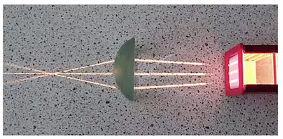
Just like lenses, curved mirrors can be used to focus light to a point or spread it out. Mirrors come in two basic shapes: concave mirrors, such as this mirror below on the left, which has a concave shape bending towards the light source, or convex mirrors, pictured below on the right, that curve away from the light source.
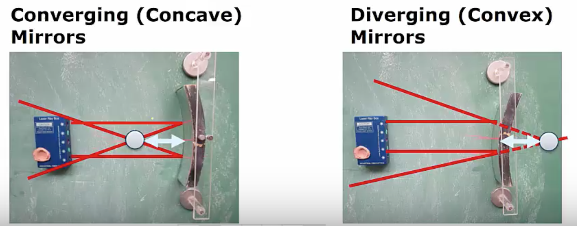
Concave mirrors are also known as converging mirrors, and convex mirrors are also known as diverging mirrors. We can see that for the concave mirror, the two light rays have converged to a point. In this sense, the concave converging mirror is functioning similarly to a converging lens; it’s taking incoming parallel light rays and converging them to a point. A common example of this particular type of mirror in use is the shaving mirror or makeup mirror that you might have in your bathroom that lets you see your face a little bit larger.
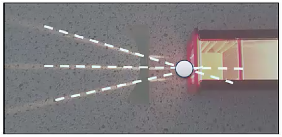
On the flip side, a convex mirror takes the incoming light rays and causes them to spread out. Just as we did with the lens, if we sort of imagine what someone to the left of the light source sees, our eyes kind of assume that light travels in straight lines, so we trace the rays back, and the light rays appear to originate from a point behind the mirror.
In this case, a convex mirror provides a very similar function to a diverging lens, taking incoming parallel light and producing outgoing light that’s diverging as if it came from some point. You can see convex mirrors quite frequently as security mirrors in buildings.
Instructor’s Note
All the mirrors we will talk about in this particular class will be called spherical mirrors, meaning the mirror is part of a sphere. Although most mirrors are not actually spherical, it turns out that studying spherical mirrors is a very good approximation for most real curved mirrors.
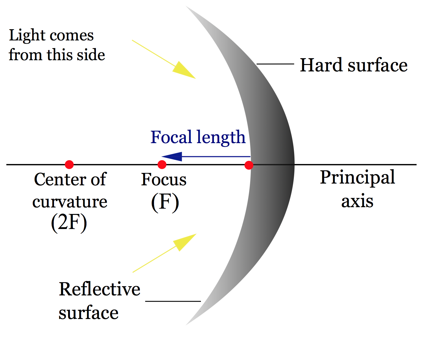
Let’s talk about focal lengths and focal points for mirrors. Just like lenses, the focal point is the point where the photons either converge to or appear to emanate from. For the concave mirror, which is converging on the left, we’ve already seen that light comes in and converges to some point; this is known as the focal point. For the diverging mirror, the light comes in and bounces off, light comes in and bounces off, and the light appears to emanate from some point behind the mirror, so this would be the focal point for this diverging mirror.
Unlike lenses, mirrors only have a single focal point, and this stems from the fact that light can go through a lens from either direction; we can put the light on either side of the lens, and the light will go through. On the other hand, a mirror only has one reflective surface; there’s only one side that will act as a mirror, and therefore mirrors only have a single focal point.
As with lenses, the focal length, which we designate  , is the distance in meters from the surface of the mirror to the focal point. For the converging lens, below on the left, this blue arrow represents the focal length and for the diverging mirror, we have this focal length below on the right.
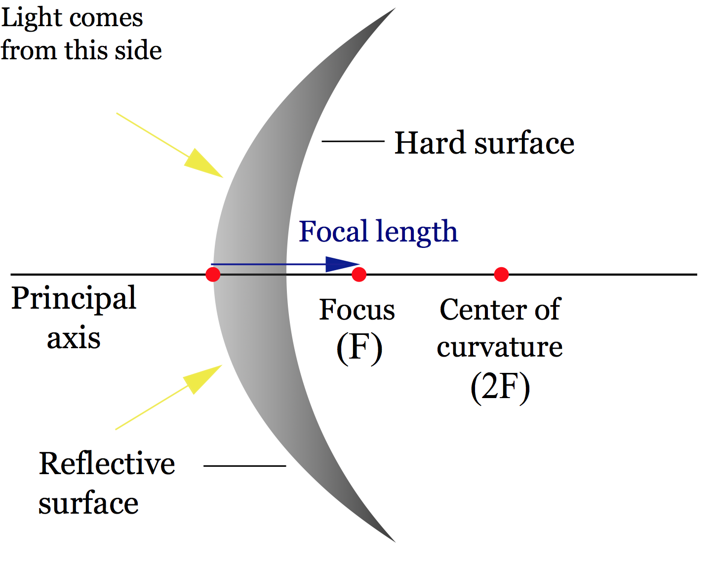
And just as with lenses, converging mirrors have a positive focal length and diverging mirrors have a negative focal length. You can start to see some similarity between mirrors and lenses. When things are converging, you have positive focal lengths, and when things are diverging, you have negative focal lengths.
Now, let’s talk a little bit about focal lengths and the radius of curvature.
Instructor’s Note
I want you to remember that all the mirrors we will be talking about here are parts of a sphere.
We need two new terms: the center of curvature, which represents the center of the sphere of which the mirror is a part, and the radius of curvature, which is the radius of which the mirror is a part.
The focal length of any spherical mirror is half the radius, so above we have a concave mirror on the top with positive focal length and a convex mirror on the bottom with negative focal length; the distance  is the radius of the sphere of which this mirror is a part, and the focal length is half that radius
 .
.
Section Summary
- Mirrors, like lenses, can be used to focus or spread out light.
- Just as with lenses, mirrors have a focal point where the photons either appear to converge to or emanate from.
- However, mirrors only have one focal point as opposed to two for lenses, which is basically due to the fact that you can’t shine light through a mirror.
- Like lenses, mirrors have a focal length, and this focal length is measured from the surface of the mirror to the focal point.
- The signs for focal length are the same for lenses and mirrors; for converging focal lengths are positive, and for diverging focal lengths are negative.
- The mirrors we will deal with in this class are parts of spheres and will have a focal length that is one half of the radius of the associated sphere, which we can write mathematically as

any lens or mirror
The apparent reproduction of an object, formed by an optical element (or collection of them) reflecting and/or refracting light.
When the image is the same orientation as the object
When the image is upside-down with respect to the object.
an imaginary line that passes through the optical element in a way that's perpendicular to it
The point where the optical axis meets the optical element
inverse of focal length
distance from the center of a lens or curved mirror to its focal point
