
3.7 Problems
3.1 Determine the equivalent resistance for the following network:

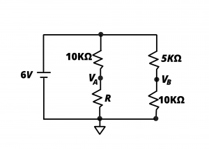
3.2 Determine the value of resistance R so that the voltages at nodes  and
and  are equal.
3.3 Design Problem: Determine appropriate values for resistors  and
and  for the voltage divider circuit shown. Specifications:
- The circuit should provide an unloaded (
 ) output voltage
  for input voltage
  .
. - The output voltage of your circuit must decrease by less than than
 % when the circuit is loaded with
  values as small as
  .
.
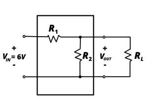
3.4 Consider again the circuit shown in figure P3.3, above. If  determine
  for the unloaded case. Repeat when the circuit is loaded with small DC motor having a resistance
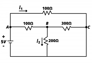
3.5 Determine the value of currents  and
and  in the following circuit:
3.6 The non-loaded, or open-circuit voltage of a certain battery is 9V. When a 100Ohm resistor is placed across the battery terminals, the voltage drops to 8.8V. Determine the battery terminal voltage when a 10Ω resistor is placed across the battery terminals. (Hint: you need to determine the series resistance internal to the battery).
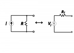
3.7 Determine the Thévenin equivalent circuit for the circuit shown in figure P3.5
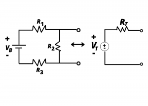
3.8 Determine the Thévenin equivalent circuit for the circuit shown in figure P3.6 if  and
and 
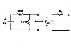
3.9 Determine the Thévenin equivalent circuit for the circuit shown in figure P3.7 if  and
and 
3.10 A GPIO output pin of an ATmega328P microcontroller (the MCU in the Arduino Uno) is rated at a maximum output current of 40 mA when the pin is HIGH (5V). Treating the pin as an ideal 5V source in series with a 40 ohm source resistance, what would be the output voltage for loads drawing (a) 10 mA, (b) 40 mA, (c) 100 mA from the output pin?
