
2 Ohm’s Law
This lab will help you to better understand the relationship between current, voltage, and resistance, which we refer to as Ohm’s Law. It will also help you to understand how current, voltage, and resistance change when placed in series and parallel circuits.
Note: This is a longer lab so it is worth 48 points total instead of the regular 24 points.
Setup Video:
Part 1: Ohm’s Law
In this part you will see how we can control the current in a circuit by varying the voltage going into the circuit and the resistance of the circuit.
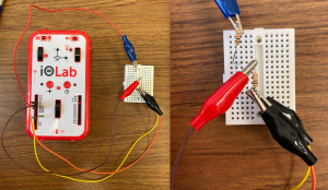
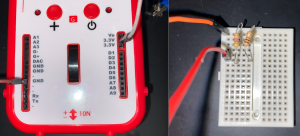
- We are going to start this lab by using the final circuit we made in the previous lab. The only thing we will change is that we will take the jumper wire out of the 3.3 V port and place it in the DAC port. This will allow us to vary the output voltage of the IOLab device. Then we can see what effect this has on the current. See Figure 1.
- You will note in this lab that the pictures show the connections somewhat differently from Lab 1. In the first lab I connected the alligator clips together so that I effectively had a longer wire with pins on both ends. The pictures in this lab show how the alligator clips can be directly connected to the resistors. Both ways do the same thing. A benefit of connecting the alligator clips directly to the resistors is that it will help ensure a good connection. I have found that the ports on the Macmillan breadboards will loosen quickly and a good connection will often not be formed. A classic sign that you have a poor connection is if you get a reading of 1.071 mV when using the High Gain Sensor.
- We are going to apply voltage to the circuit at 0.5 V intervals between 0 V and 3.0 V. To do this, choose the High Gain Sensor in the IOLab software. Then click on “Remote 1” above the graph and choose “Output” from the dropdown menu. The click “DAC”. See Figure 2.

- To the left of the graph you will now see a section called “Output”. Click the “On” button. See Figure 3.

- The voltage is initially set to 0.0 V.
- As we change the output voltage we will use the High Gain sensor to measure the corresponding current flowing through the circuit. Recall that the High Gain sensor has an “offset voltage”. To compensate for this offset in the previous lab we took two measurements and averaged them. However when using the DAC output we can actually measure this offset voltage. Since 0.0 V is the default output voltage we can click Record on the High Gain sensor and the reading we get IS the offset voltage. Record the offset voltage. Q1.1: What is the offset voltage of your High Gain sensor?
- Each IOLab device has a different offset voltage. But if, for instance, the High Gain sensor reading is -0.055 mV, then your offset voltage is -0.055 mV. This means that the true voltage for each measurement you take is going to be 0.055 mV more than what the High Gain sensor is displaying. So for every measurement you take from the High Gain sensor you will need to add the offset voltage to the High Gain sensor reading to get the true voltage. If we use the example where the offset voltage is -0.055 mV, then adding 0.055 mV to that will give us 0 V, which we know to be the true voltage. Then since we are measuring the voltage over the 1 Ω resistor, we know that the current will have the same value. So when there is 0 mV of voltage then there is 0 mA of current.
- Now change the output voltage to 0.5 V and record the current using the High Gain sensor. Remember to add the offset voltage to the reading to get the true voltage and hence the true current. Record the current at 0.5 V.
- Continue to increase the voltage at 0.5 V intervals up through 3.0 V and measure the current at each of these intervals. Record the current measurements in a table like the one below. Q1.2: Show your current measurements at 0.5 V increments.

- Use the data you collected to make a graph of Voltage versus Current. Q1.3: Upload your graph of voltage versus current. Q1.4: What type of graph do you get? (Linear, exponential, etc.) Q1.5: Are voltage and current directly or indirectly proportional to one another?
- The slope of your graph tells us the proportionality constant between current and voltage. This constant depends on the only other element in the circuit, the resistors. Other than the voltage source, this circuit only has two resistors. Remember that in this circuit almost all of the voltage goes to the 10 kΩ resistor and essentially nothing goes to the 1 Ω resistor. The 1 Ω resistor is irrelevant other than to give us a way to determine the current. So the circuit effectively only consists of a voltage source and a 10 kΩ resistor. So the proportionality constant is the resistance of this one resistor. Hence Ohm’s Law, V = I R. But the resistors in your kit are rather cheap so they usually don’t have the exact amount of resistance as advertised. By finding the slope of the line you graphed you can determine a more accurate resistance of this resistor. Q1.6: What is the true resistance of the 10 kΩ resistor?
- So far we have seen that if we want to increase the current through a circuit we can increase the voltage. Changing the resistance will also change the current flowing through the circuit. Replace the 10 kΩ resistor with a 4.7 kΩ resistor. (The resistor bag with MPN ending in J0472 contains the 4.7 kΩ resistors.)
- Apply a voltage of 3.0 V and measure the current flowing through the 4.7 kΩ resistor and compare it to the current that flowed through the 10 kΩ resistor. Q1.7: What is the current flowing through the 4.7 kΩ resistor when 3.0 V are applied to it? Q1.8: What effect does decreasing the resistance have on the current flowing through a circuit?
Part 2: Series Circuits
In this part you will determine how voltage, current, and resistance behave when placed in a series circuit.
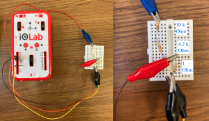
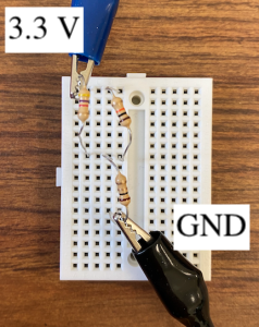
- A series circuit only contains one path for the current to flow through. Technically all of the circuits that we have made in this lab so far have been series circuits. The 10 kΩ resistor and the 1 Ω resistor were in series because the current only flowed through one path. The current had to flow through the 10 kΩ resistor before it flowed through the 1 Ω resistor. The current was only given the option to travel through one path. Since it only flows through one path, we can conclude that the current is the same everywhere in a series circuit. But since the 1 Ω resistor was so much smaller than the 10 kΩ resistor it was only useful to place it in the circuit as a way to measure current. So let’s create a new circuit that contains a 10 kΩ resistor in series with a 4.7 kΩ resistor and a 1 Ω resistor. See the setup in Figure 4.
- Use the method you learned in Part 1 (where you plotted a graph) to determine the actual total resistance of this circuit. Q2.1: What is the actual total resistance of the circuit containing the 10 kΩ resistor and the 4.7 kΩ resistor? Q2.2: What can you conclude about the way resistors behave when placed in series? Q2.3: What can you conclude about the way current behaves in a series circuit?
- We call the total resistance that the circuit has “Equivalent Resistance” and symbolize it with
 . Let’s call the 10 kΩ resistor
  and the 4.7 kΩ resistor
  . Q2.4: Write a generic equation for determining equivalent resistance in series circuits.
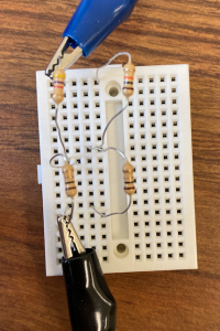
 - Now we will examine how voltage behaves in a series circuit. To do this we will remove the 1 Ω resistor and use the 3.3 V power source and the Analog 7 sensor again. Setup the circuit as shown in Figure 5.
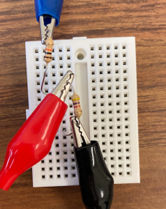
- Use the Analog 7 sensor to record the voltage drop across the 4.7 Ω resistor.
- Now use the Analog 7 sensor to record the voltage drop across the 10 k Ω resistor. See figure 6 and note the difference between Figures 5 and 6. The order of the resistors must be changed in order to read the correct voltage drop. Q2.5: What are the voltage drops across the 4.7 Ω and the 10 kΩ resistors?
- Q2.6: What can you conclude about the way voltage works in series circuits? (Remember that the total output voltage now is 3.3 V since you are using the 3.3 V port.)
Part 3: Parallel Circuits
Finally you will determine how voltage, current, and resistance behave when placed in a parallel circuit. In a series circuit there was only one pathway for the current to flow through. In parallel circuits there is more than one pathway.
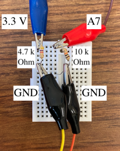
- We’ll start off by determining how voltage behaves in a parallel circuit. Place a 10 kΩ resistor and a 4.7 kΩ in parallel as shown in Figure 7.
- Now the current can flow through both resistors at the same time. We need to measure the voltage drop over each resistor separately. Figure 8 shows how to connect your circuit to the IOLab device to measure the voltage drop over the 10 kΩ resistor.
- Now you can record the voltage drop across the 10 kΩ resistor using the Analog 7 sensor. Then switch the placement of the resistors to measure the voltage drop across the 4.7 kΩ resistor. Q3.1: What are the voltage drops across the 4.7 kΩ and 10 kΩ resistors? Q3.2: What can you conclude about the way voltage from the power source is delivered to resistors in parallel circuits?
- Now let’s measure the current flowing through the circuit. We can do this similar to how we measured current in a series circuit. We can place a 1 Ω resistor in series with these resistors. In Figure 9 you can see that this was done by placing one end of the 1 Ω resistor in row 7 and the other end in row 12. Then the GND wire was moved to row 12.
- Now you can measure the current through the circuit using the High Gain sensor. Plug your jumper cable with alligator clip wires into the High Gain sensor and attach the alligator clips to the 1 Ω resistor. Remember that you have to take two measurements with the High Gain sensor wires reversed and average to get the true current (remember to average the absolute values of these measurements). Q3.3: What is the current flowing through the parallel circuit?
- Now you will want to measure the current flowing through each resistor and see how these values compare to the total current flowing through the circuit. To do this you will need another 1 Ω resistor to act as a second Ammeter. Figure 10 shows one way to do this. You can see that one end of the resistor on the left was moved from row 7 to row 8. Then the second 1 Ω resistor is connected to row 8 and 12.
- Now measure the current flowing through each resistor. Q3.4: What is the current flowing through the 4.7 kΩ resistor and the 10 kΩ resistor? Q3.5: What can you conclude about the way current works in a parallel circuit?
- Finally you can determine how resistance works in a parallel circuit. Since you know the voltage output and the total current flowing through the entire parallel circuit you can use Ohm’s Law to calculate the equivalent resistance of the circuit. How does this differ from how resistors work in series circuits? Q3.6: What is the equivalent resistance of the parallel circuit? How does resistance work in a parallel circuit?
Summary
Resistance
We can derive an equation for equivalent resistance in parallel circuits. In this part of the lab you saw that voltage is the same everywhere in a parallel circuit but the total circuit current gets split up between the resistors in the circuit. For the circuit we set up we can express this mathematically as  where I is the total current flowing through the circuit, is the 4.7 kΩ resistor, is the 10 kΩ resistor and V represent the total voltage supplied by the 3.3 V port. The resistance, R, is equivalent to
  according to Ohm’s Law. So if we factor out the V to separate it from and then we can rearrange the equation such that we get on one side and just and on the other side. First we factor out the V:

Then move I to the right side and and to the left side:

Since  where R is the total or equivalent resistance, we can rewrite this as:

Then we can clean this up a bit by moving and to the right side and to the left side:

And if we have more than 2 resistors we can just add more  to the right side.
This is a bit messier that how resistor work in series circuits but depending on what you are trying to get your circuit to do you may want to place resistors in series for one situation but in parallel for another. If you need a circuit to have a resistance of 30,000 Ω then you could place three 10 kΩ resistor in series to accomplish this. This is important since 30,000 Ω resistors are far less common than a 10 kΩ resistor. It may be that you need a resistor of a common resistance but you don’t happen to have that resistor on hand in your maker space or electronics lab. Placing resistors in series allows us to add more resistance to a circuit. You also saw that placing resistors in parallel creates an equivalent resistance that is smaller than either of the two resistors you used. So now matter what resistance you need, you can manipulate the circuit by placing the resistors in series and/or parallel to get the resistance that you want. Once you are done prototyping and know the resistance you need and are ready to mass produce, then you can special order the exact resistance resistor that you need.
Voltage
In series circuit, the voltage is split up among the resistors. In parallel, the voltage is the same everywhere. Again, depending on what you are trying to do, you may want to place resistors in series and/or parallel. For instance, if you want to hook up several light bulbs (light bulbs can be considered resistors since they resist the flow of current and obey Ohm’s Law) but don’t want them to be really dim, would you connect them in series or parallel?
Current
In series circuits, the current is the same everywhere in the circuit. In parallel, the current gets split up. Current controls the rate of flow of electrons. When I plug my electric car into a regular 120 V electric outlet, I can get 10 Amps of current to flow to charge the battery and it can take 30 hours to charge it from 20-80%. But if I want to charge it faster I can plug it into a 240 V outlet that is capable of providing 32 Amps of current. This will charge the car up the same amount in 5 hours.
Grading Rubric:
Points are assigned for each question according to the following:
| 1.1 | 2 Points – A reasonable voltage is provided AND appropriate units are included.
1 Point – A reasonable voltage is provided OR appropriate units are included. 0 Points – A reasonable voltage is NOT provided AND appropriate units are NOT included. |
| 1.2 | 7 Points – The table is complete AND reasonable voltages are provided AND appropriate unites are used.
5 Points – The table is complete AND reasonable voltages are provided BUT appropriate units are not used. 3 Points – The table is partially complete AND reasonable voltages are provided. 0 Points – The table is not complete OR reasonable voltages are NOT provided. |
| 1.3 | 2 Points – An accurate graph of voltage versus current is present AND the graph is zoomed in appropriately.
1 Point – An accurate graph of voltage versus current is present BUT the graph is NOT zoomed in appropriately. 0 Points – An accurate graph of voltage versus current is NOT present. |
| 1.4 | 2 Points – The correct type of graph is identified.
0 Points – The correct type of graph is NOT identified. |
| 1.5 | 2 Points – The correct relationship is identified.
0 Points – The correct relationship is NOT identified. |
| 1.6 | 2 Points – The resistance stated is within 20% of the advertised resistance AND appropriate units are used.
1 Point – The resistance stated is within 20% of the advertised resistance OR appropriate units are used. 0 Points – The resistance stated is NOT within 20% of the advertised resistance AND appropriate units are NOT used. |
| 1.7 | 2 Points – The current stated is within 20% of the correct current AND appropriate units are used.
1 Point – The current stated is within 20% of the correct current OR appropriate units are used. 0 Points – The current stated is NOT within 20% of the correct current AND appropriate units are NOT used. |
| 1.8 | 2 Points – The correct effect is fully identified.
1 Point – The correct effect is partially identified. 0 Points – The correct effect is NOT identified. |
| 2.1 | 2 Points – The resistance stated is within 20% of the total advertised resistances AND appropriate units are used.
1 Point – The resistance stated is within 20% of the total advertised resistances OR appropriate units are used. 0 Points – The resistance stated is NOT within 20% of the total advertised resistances AND appropriate units are NOT used. |
| 2.2 | 2 Points – An accurate statement of how resistors behave in series is present.
1 Point – A partially accurate statement of how resistors behave in series is present. 0 Points – An accurate statement of how resistors behave in series is NOT present. |
| 2.3 | 2 Points – An accurate statement of how current behaves in series is present.
1 Point – A partially accurate statement of how Current behaves in series is present. 0 Points – An accurate statement of how current behaves in series is NOT present. |
| 2.4 | 2 Points – An accurate equation is provided.
1 Point – A partially accurate equation is provided. 0 Points – An accurate equation is not provided. |
| 2.5 | 2 Points – The voltages across BOTH resistors are within 20% of the correct voltages.
1 Point – The voltage across only ONE resistor is within 20% of the correct voltage. 0 Points – The voltage across NEITHER resistor is within 20% of the correct voltage. |
| 2.6 | 2 Points – An accurate statement of how voltage behaves in series is present.
1 Point – A partially accurate statement of how voltage behaves in series is present. 0 Points – An accurate statement of how voltage behaves in series is NOT present. |
| 3.1 | 2 Points – The voltages across BOTH resistors are within 20% of the correct voltages.
1 Point – The voltage across only ONE resistor is within 20% of the correct voltage. 0 Points – The voltage across NEITHER resistor is within 20% of the correct voltage. |
| 3.2 | 3 Points – An accurate statement of how voltage behaves in parallel is present.
1.5 Points – A partially accurate statement of how voltage behaves in parallel is present. 0 Points – An accurate statement of how voltage behaves in parallel is NOT present. |
| 3.3 | 2 Points – The current stated is within 20% of the correct current AND appropriate units are used.
1 Point – The current stated is within 20% of the correct current OR appropriate units are used. 0 Points – The current stated is NOT within 20% of the correct current AND appropriate units are NOT used. |
| 3.4 | 2 Points – The currents across BOTH resistors are within 20% of the correct currents.
1 Point – The current across only ONE resistor is within 20% of the correct current. 0 Points – The current across NEITHER resistor is within 20% of the correct current. |
| 3.5 | 3 Points – An accurate statement of how current behaves in parallel is present.
1.5 Points – A partially accurate statement of how Current behaves in parallel is present. 0 Points – An accurate statement of how current behaves in parallel is NOT present. |
| 3.6 | 3 Points – The resistance stated is within 20% of the correct equivalent resistance AND an accurate statement of how resistors behave in parallel is present.
1.5 Points – The resistance stated is within 20% of the correct equivalent resistance OR an accurate statement of how resistors behave in parallel is present. 0 Points – The resistance stated is NOT within 20% of the correct equivalent resistance AND an accurate statement of how resistors behave in parallel is NOT present. |