
Digikey Version Lab 4
Digikey Equipment Version
Lab 4 Report Worksheet (Digikey Version)
In this lab we will observe how a voltage can be “induced” in a stationary loop of wire by moving a magnet near it. A current flowing through a loop of wire or coil will create its own magnetic field. A voltage can also be induced in the loop if we move it near a stationary magnet. This is a very small amount of voltage so we will need to use the High Gain sensor to be able to see this induced voltage. Finally we will see how a voltage in one loop can induce a voltage in another loop.
Part 1: Moving Magnets and Current
In this part we will observe an induced voltage in a loop when we move a permanent magnet near it.
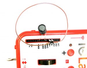
- Take one of your jumper wires and form it into a loop. This will not be a perfect loop since we will have to plug the pins into the High Gain sensor ports. See Figure 1.

- Hold the IOLab device so that you can drop the magnet through the center of the loop. You will want to hold the IOLab device above your desk so that the magnet doesn’t bounce back up through or near the loop after it falls through. Begin recording and then drop the magnet through the loop and observe the High Gain sensor graph. Recall that the High Gain sensor measures very small amounts of voltage.
- Then drop the magnet from different heights above the loop and observe how the induced voltage changes depending on how fast the magnet moves through the loop. What relationship exists between the magnet’s speed and the voltage induced in the loop? When the magnet falls through the loop there are 2 peak voltages in opposite directions. Why? Carefully compare these peak voltages. Are they exactly the same? Why or why not?
- Try placing the magnet near the center of the loop. What is the voltage if you place the magnet at rest in the loop? What does this indicate is necessary in order to get a current from a magnet?
Part 2: Moving Coils and Current
In this part we will see how moving a loop near a stationary permanent magnet will also induce a voltage.
- Move the loop around different parts of the magnet and observe what happens to the induced voltage. Also try to bring different sides of the loop near the magnet to see what happens. Is it necessary for a magnet to move to get a current from a loop? Why or why not?
- What is different about the voltage when you bring the loop near one pole of the magnet as opposed to the other pole?
- What happens when you push one pole of the magnet toward the top of the loop as opposed to when you push the same pole of the magnet toward the bottom of the loop? What does this difference have to do with the magnetic field?
Part 3: Circuits and Current
In this part we will see how a coil itself can create its own magnetic field. An inductor is a coil with many turns.
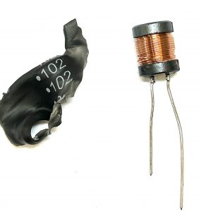
- Hook up the 1 mH Inductor to the DAC and GND ports so we can apply voltage to it. This is Part Desc: FIXED IND 1MH. The inductor has some plastic wrapping that can be easily and safely taken off if you want to see that it is made up of some very thin, insulated wire that is wound around many times. See Figure 2a. In order for the High Gain sensor to collect data coming from this coil we will need to use a “pick up” coil. We can just use the loop from Parts 1 and 2 to do this. You will just want to try to center the loop around the inductor as best you can. See Figure 2b. If you have the pick up coil placed as in figure 2, then positive readings on the High Gain sensor will indicate that the current is flowing clockwise and negative readings will indicate that the current is flowing counterclockwise.
 |
 |
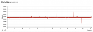
- Set the DAC output to 3.3 V and begin recording with the High Gain sensor. (Click on the Settings button above the graph and choose Expert Mode > Output configuration. Then you will find the DAC output control under the sensor list. See steps 2 and 3 in Part 1 of the Ohm’s Law lab if you need a refresher on setting up the DAC output.) Then place your coil above the inductor and turn the DAC output on and off several times and observe what happens. Since the voltage will be very small, even for the High Gain sensor, you will have to zoom in quite a bit to see what is happening. Figure 3 shows how much I zoomed in. You’ll want to start recording before zooming in. Remember that the initial voltage reading will be the offset voltage and not zero. How is turning the power off different from turning it on?
- Finally, reverse the direction of the inductor by swapping the leads plugged into the DAC and Ground ports. Then turn the DAC output on and off and observe what happens. What changes when you flip the direction of the inductor and turn the power on and off? Why does it change? Why does turning the power on and off produce a current in the pick up coil but there is no current while the power continues to be on?