1 Circuit Basics
Below you will find the Instructions for how to complete this lab. The responses you need to submit are highlighted in blue. You will need to submit these responses in the Gradescope assignment called Lab 1. See the grading rubric at the end of each lab page to see how you will be graded.
You can access the rest of the labs as well as the Getting Started page and the Useful Links page by clicking on the Contents dropdown menu in the upper left part of this page.
Setup Video:
This lab will help you to understand how the basic circuit elements can be used to create electrical circuits and how to measure voltage and current in a circuit.
Connections
In order to create electric circuits we need to form pathways for the current to flow. The breadboard is a convenient tool to help us form temporary pathways that can easily be changed. When you examine the breadboard you will notice that it has a gap that divides it in half. Let’s consider the side that has columns labeled a through e and rows numbered 1 through 17. This is the part of the breadboard that we are going to be using extensively in the circuitry labs. Row 1 has 5 holes, or “ports”. We can identify each port as 1A, 1B, 1C, 1D, and 1E. All of these ports are connected. The same is true for row 2. All five or its ports are connected. And this pattern continues all the way down to row 17. The other side of the breadboard with columns f through j is connected in the same way.
“Jumper Wires” will also allow us to make connections with other parts of the circuit. Your accessory pack has several of these wires which have a pin on one end and an alligator clip on the other end. These clips can often be useful when a breadboard is not present.
Resistance
A resistor is anything that resists the flow of electrical energy. Your accessory pack contains several resistors of varying resistance. In this lab we will use two 10,000 Ohm (10 kΩ) resistors and a 1 Ohm (1 Ω) resistor. The resistors in your accessory pack are in bags labeled with the Manufacturer’s Product Number (MPN). The 1 Ω resistor’s MPN ends in J0109 and the 10 kΩ resistor’s MPN ends in J0103.
An LED also contains a certain amount of resistance. Unlike regular resistors, however, LEDs do not adhere to Ohm’s Law. In this lab we will use the red LED in your lab kit, but since it doesn’t follow Ohm’s Law we will not perform any quantitative measurements on it.
The resistance of the jumper wires is so low that we can effectively treat them as having no resistance at all.
Power Sources
There are many sources of power all around us. If you want to watch television you usually have to get the power to run the tv from an electrical wall outlet. Other devices like your cell phone simply need a battery to be used. These are two of the most common power sources that we typically use. We will use the AA batteries in the IOLab device for our power source for all of our labs.
As you likely know, a battery contains a positive end and a negative end. The positive end of the batteries in the IOLab device corresponds to the “3.3 V” ports. The negative end corresponds to the “GND” ports.
Part 1: Powering an LED
The first circuit we will create will be just a simple one to light up an LED.
Note: The IOLab device will shut off automatically after a few minutes if it is not being used.
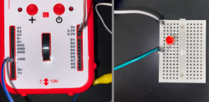
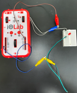
- Place the red LED in the breadboard as shown in Figure 1. I have placed the long end of the LED in Row 1 Column c and the short end in Row 9 Column c.
- Clip two of the alligator clips together so that you form a wire with pins on both ends. Then connect one of the 3.3 V ports on the IOLab device to any other hole in Row 1. (Column a, b, d, or e)
- In the same way as step 2, connect one of the GND ports on the IOLab device to Row 9.
- Now you can open the IOLab software and power on the IOLab device. (These labs assume that you have used the IOLab device and software for Physics 131 lab. If you didn’t, go to the “Getting Started” page to learn how to access and use the software.) You will know that you connected everything properly if the LED lights up. Take a picture of your completed circuit while the LED is on. Q1: Upload a picture of your circuit with the LED on.
Part 2: Measuring Voltage
To measure voltage in a circuit we use a Voltmeter. A Multimeter is a device that is typically used to measure quantities like voltage, resistance, and current. The IOLab device, however, has its own built in voltmeter so we will use it to measure the voltage in our circuits.
- Replace the LED with one of the 10 kΩ resistors. It doesn’t matter which ends of the resistor connect to the 3.3 V and GND ports. Then connect one end to the A7 port on the IOLab device and the other end to a free port in Row 1. See Figure 2.
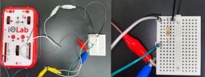
- From the sensor list in the software choose the “Analog 7” sensor. This sensor measures the voltage between the location it is connected to on the breadboard and the location where the GND wire is connected. So by connecting the A7 port to Row 1 we are measuring the voltage across the resistor. We also refer to this as a voltage “drop”.
- Click record and allow it to collect data for a few seconds. You should see a flat line at 3.3 V. Use the Select region tool to click and drag over this data to find the average voltage. (Remember that the average is represented by 𝜇.) Record this voltage. Q2.1: What is the average output voltage of your IOLab device?
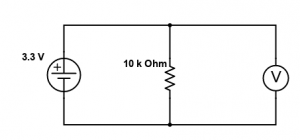
- Since the resistor is the only element with significant resistance in the circuit, the average voltage that you recorded is the voltage output of the IOLab device. This is always the output voltage of the IOLab device from the 3.3 V port. We can now complete a schematic diagram of this setup. See Figure 3.
- Since you know the resistance of the resistor and voltage drop across the resistor you can now use Ohm’s Law to determine the current flowing through the circuit. As you will learn in the next lab, Ohm’s Law states that voltage (V) equals current (I) times resistance (R) or V = I R. Q2.2: Calculate the current flowing through the 10 k Ω resistor.
Part 3: Series Circuits
A series circuit has only one path for the current to flow through. This means that the current is the same at every location in a series circuit but the voltage gets split up among all of the circuit elements. We will start by making a series circuit that contains two 10 kΩ resistors. See Figure 4.
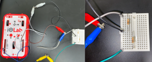
- Set up the circuit in Figure 4. We can refer to the original 10 kΩ resistor as R1 and the new one as R2. You can see that I placed one end of the second resistor in Row 9 and the other end in Row 17. I also moved the GND wire to Row 17.
- Now move the A7 wire to Row 9. This will allow us to measure the voltage drop over R2. Record the voltage drop over R2. Q3.1: What is the voltage drop over R2?
- Measure the voltage drop across the whole circuit. Q3.2: How does the voltage drop over R2 voltage compare with the voltage drop across the whole circuit? How should it compare?
- Now remove resistor R2 and replace it with a 1 Ω resistor. Try to use the Analog 7 sensor to measure the voltage drop across the 1 Ω resistor. The average voltage reading should be 0. Since this resistor has 10,000 times less resistance than R1 only a very tiny fraction of the IOLab’s output voltage will be delivered to it. This tiny amount of voltage is beyond the range that the Analog 7 sensor can accurately measure.
- Q3.3: Calculate what the voltage across the 1 Ω resistor should be.
- The “High Gain” sensor, however, is capable of measuring very small amounts of voltage. To use this sensor we can move the wire connected to A7 to the G+ port. Then connect a new wire to the G- port to Row 17. See Figure 5.
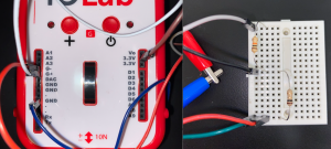
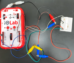
- Add a new acquisition set and choose the High Gain sensor. This sensor measures in units of mV (milli Volts). Allow the software to record for a few seconds and then record the average voltage. Q3.4: What is the voltage drop across the 1 Ω resistor as measured with the High Gain sensor?
- The High Gain sensor does not come without flaws though. It has what we can call an “offset voltage”. The way to get around this issue is to reverse the jumper wires in the G+ and G- ports and take a second measurement. Record the second measurement. Q3.5: What is the voltage drop across the 1 Ω resistor as measured with the High Gain sensor? (Second measurement) Then the average of these two measurements will give you the true voltage across the resistor. When averaging, make sure to average the magnitudes of the measurements since one will be positive and one will be negative. Record this true voltage. Q3.6: What is the true voltage across the 1 Ω resistor? (You’ll want to keep this circuit set up since we will continue using it in the next lab.)
Part 4: Measuring Current
Although it is difficult to accurately measure the voltage across a 1 Ω resistor, placing one in series with another circuit element has a very useful application.
- Q4: Calculate the current flowing through the 1 Ω resistor. Since
 and the resistance is 1 Ω, the current and voltage have the same numerical value. And since this is a series circuit, this is the current everywhere in the circuit. By placing the 1 Ω resistor in series with the 10 kΩ resistor, we turned the 1 Ω resistor into an Ammeter, a device that measures current in a circuit. Since the resistance of the 1 Ω resistor is negligible in comparison to the resistance of the 10 kΩ resistor, its presence in the circuit doesn’t really change what the current would have been if it wasn’t present in the circuit. It just gives us a way to be able to measure the current in a circuit. So if the voltage on the high gain sensor reads 0.1 mV, then the current through the circuit is 0.1 mA.
Grading Rubric:
Points are assigned for each Gradescope assignment question according to the following:
| 1 | 3 Points – There is a picture of the circuit with the LED on.
2 Points – There is a picture of the circuit but the LED is off. 0 Points – No picture is uploaded. |
| 2.1 | 3 Points – The voltage stated is within 10% of the correct voltage AND appropriate units are used.
2 Points – The voltage stated is within 10% of the correct voltage BUT appropriate units are not used. 1 Point – The voltage stated is NOT within 10% of the correct voltage BUT appropriate units are used. 0 Points – The voltage stated is NOT within 10% of the correct voltage AND appropriate units are not used. |
| 2.2 | 3 Points – The current stated is within 10% of the correct current AND appropriate units are used.
2 Points – The current stated is within 10% of the correct current BUT appropriate units are not used. 1 Point – The current stated is not within 10% of the correct current BUT appropriate units are used OR calculations were shown. 0 Points – The current stated is not within 10% of the correct current AND appropriate units are not used AND calculations were not shown. |
| 3.1 | 2 Points – The voltage stated is within 10% of the correct voltage AND appropriate units are used.
1 Point – The voltage stated is within 10% of the correct voltage OR appropriate units are used. 0 Points – The voltage stated is not within 10% of the correct voltage AND appropriate units are not used. |
| 3.2 | 2 Points – An accurate comparison is made AND there is a correct explanation of how it should compare.
1 Point – An accurate comparison is made OR there is a correct explanation of how it should compare. 0 Points – An accurate comparison is not made AND there is an inaccurate explanation of how it should compare. |
| 3.3 | 2 Points – The voltage stated is within 10% of the correct voltage AND appropriate units are used.
1 Point – The voltage stated is not within 10% of the correct voltage BUT appropriate units are used OR calculations were shown. 0 Points – The voltage stated is not within 10% of the correct voltage AND appropriate units are not used AND calculations were not shown. |
| 3.4 | 2 Points – The voltage stated is within 10% of the correct voltage AND appropriate units are used.
1 Point – The voltage stated is within 10% of the correct voltage OR appropriate units are used. 0 Points – The voltage stated is not within 10% of the correct voltage AND appropriate units are not used. |
| 3.5 | 2 Points – The voltage stated is within 10% of the correct voltage AND appropriate units are used.
1 Point – The voltage stated is within 10% of the correct voltage OR appropriate units are used. 0 Points – The voltage stated is not within 10% of the correct voltage AND appropriate units are not used. |
| 3.6 | 2 Points – The voltage stated is within 10% of the correct voltage AND appropriate units are used.
1 Point – The voltage stated is within 10% of the correct voltage OR appropriate units are used. 0 Points – The voltage stated is not within 10% of the correct voltage AND appropriate units are not used. |
| 3 Points – The current stated is within 10% of the correct current AND appropriate units are used.
2 Points – The current stated is within 10% of the correct current BUT appropriate units are not used. 1 Point – The current stated is not within 10% of the correct current BUT appropriate units are used OR calculations were shown. 0 Points – The current stated is not within 10% of the correct current AND appropriate units are not used AND calculations were not shown. |
